Functional safety
326
9.
FUN
C
TI
ON
AL SAFET
Y
Cabl
ing
an
d
groun
din
g
322
DDS
HARDWARE
Ref.1310
9.8 Cabling and grounding
S
afe
T
orque
O
ff (STO)
The following recommendations must be taken into account when design-
ing the STO safety function:
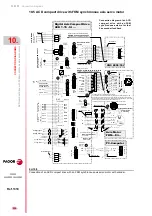
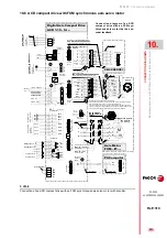
A fuse MUST be installed that can limit the current of at least the STO
channel input of the AXD/SPD drive (pin 2 “Drive Enable” of X2).
FAGOR recommends installing a “1 A” slow fuse to limit the input cur-
rent through this pin. In the case of the figure where a safety relay has
been used, the fuse may be installed on the 24 V DC line to activate
both the AXD/SPD input and the external main contactor so it also
protects the internal contacts of the safety relay.
Try keeping power cables and signal cables apart from each other.
Run the STO channels activating cables through separate conduits
Install an intermediate auxiliary relay to activate the coil of the contac-
tor for high power units were the consumption current and peak cur-
rent of the external main contactor is significant; although the mirror
contact in series with the start button must belong to the external main
contactor. Never to the intermediate relay.
DDS system in general
The instructions regarding the cabling and grounding when installing Fa-
gor Automation's Digital Drive System are described
in chapter
in this manual.
Summary of Contents for DDS
Page 1: ...DRIVE DDS Hardware manual Ref 1310...
Page 6: ...I 6 DDS HARDWARE Ref 1310...
Page 9: ......
Page 10: ......
Page 11: ......
Page 12: ......
Page 16: ...16 Ref 1310 DDS HARDWARE...
Page 30: ...1 DESCRIPTION 30 Description DDS HARDWARE Ref 1310...
Page 94: ...2 POWER SUPPLIES 94 Power supplies DDS HARDWARE Ref 1310...
Page 188: ...3 DRIVE MODULES 188 Drive modules DDS HARDWARE Ref 1310...
Page 204: ...4 AUXILIARY MODULES 204 Auxiliary modules DDS HARDWARE Ref 1310...
Page 232: ...SELECTING CRITERIA 5 232 Selection criteria DDS HARDWARE Ref 1310...
Page 266: ...7 CABLES 266 Cables DDS HARDWARE Ref 1310...
Page 312: ...8 INSTALLATION 312 Installation DDS HARDWARE Ref 1310...
Page 326: ...9 FUNCTIONAL SAFETY 326 Functional safety DDS HARDWARE Ref 1310...
Page 354: ...10 CONNECTION DIAGRAMS 354 Connection diagrams DDS HARDWARE Ref 1310...
Page 378: ...12 SALES REFERENCES 378 Sales references DDS HARDWARE Ref 1310...
Page 384: ...13 COMPATIBILITY 384 Compatibility DDS HARDWARE Ref 1310...
Page 385: ......


