·268·
Programming manual
CNC 8055
CNC 8055i
11.
IRREGULAR POC
K
ET CANNED CYCLE
·M· & ·EN· M
ODELS
S
OFT
: V02.2
X
3D pockets
11.2.8
Profile programming syntax
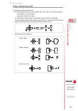
The outside profile and the inside profiles or islands which are programmed must be defined by
simple geometrical elements such as straight lines or arcs.
The first definition block (where the external profile starts) and the last (where the last profile defined
ends) must be provided with the block label number. These label numbers will indicate the beginning
and end of the profile geometry definition for the profiles that make up the pocket.
The profile programming syntax must follow these rules:
• The first profile defining block must have a label number to indicate to the G66 canned cycle
the beginning of the geometry description.
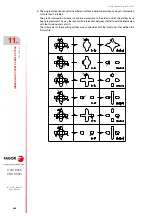
• First, the outside pocket contour must be defined and, then, the contour of each island.
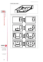
When a contour has more than one depth profile, the contours must be defined one by one
indicating, on each one, the plane profile and, then, its depth profile.
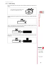
• The first profile defining block of the plane profile as well as that of the depth profile must contain
function G00 (indicative of the beginning of the profile).
Care must be taken to program G01, G02 or G03 in the block following the definition of the
beginning, as G00 is modal, thus preventing the CNC from interpreting the following blocks as
the beginnings of a new profile.
• The last profile defining block must have a label number to indicate to the G66 canned cycle the
end of the geometry description.
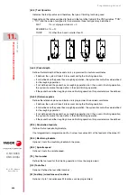
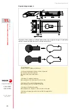
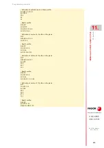
; Definition of irregular pocket canned cycle.
G66 R100 C200 F300 S400 E500
; Geometrical description.
N400 G17
...
N500 G2 G6 X300 Y50 I150 J0
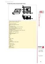
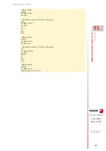
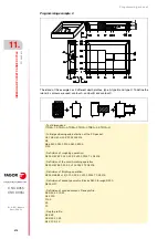
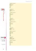
; Definition of irregular pocket canned cycle.
G66 R200 C250 F300 S400 E500
; Beginning of the definition of pocket geometry.
N400 G17
; External contour. Plane profile.
G0 G90 X5 Y-26 Z0
--- --- --- ---
; Depth profile.
G16 XZ
G0 --- ---
--- --- --- ---
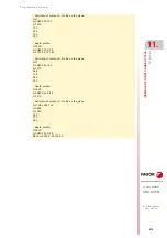
; Island definition
G17
; Plane profile.
G0 X30 Y-6
--- --- --- ---
; Depth profile.
G16 XZ
G0
--- --- --- ---
; End of geometric description.
N500G3 Y-21 Z0 J-5 K0
Summary of Contents for 8055 EN
Page 1: ...CNC 8055 M EN Programming manual Ref 1711 Soft V02 2x...
Page 8: ...8 Programming manual CNC 8055 CNC 8055i SOFT V02 2X...
Page 12: ...12 CNC 8055 CNC 8055i Declaration of conformity and Warranty conditions...
Page 16: ...16 CNC 8055 CNC 8055i Version history...
Page 22: ...22 CNC 8055 CNC 8055i Returning conditions...
Page 24: ...24 CNC 8055 CNC 8055i Additional notes...
Page 26: ...26 CNC 8055 CNC 8055i Fagor documentation...
Page 448: ......
Page 464: ...464 Programming manual CNC 8055 CNC 8055i D M EN MODELS SOFT V02 2X Key code...
Page 466: ...466 Programming manual CNC 8055 CNC 8055i D M EN MODELS SOFT V02 2X Key code MC operator panel...
Page 467: ...Programming manual CNC 8055 CNC 8055i D M EN MODELS SOFT V02 2X 467 Key code...
Page 468: ...468 Programming manual CNC 8055 CNC 8055i D M EN MODELS SOFT V02 2X Key code...
Page 471: ...Programming manual CNC 8055 CNC 8055i D M EN MODELS SOFT V02 2X 471 Key code 11 LCD Monitor...
Page 472: ...472 Programming manual CNC 8055 CNC 8055i D M EN MODELS SOFT V02 2X Key code...
Page 478: ...478 Programming manual CNC 8055 CNC 8055i F M EN MODELS SOFT V02 2X Maintenance...
Page 479: ...Programming manual CNC 8055 CNC 8055i F SOFT V02 2X 479...
Page 480: ...480 Programming manual CNC 8055 CNC 8055i F SOFT V02 2X...
Page 481: ......


