·160·
Programming manual
CNC 8055
CNC 8055i
9.
CANN
ED
CYCLES
·M· & ·EN· M
ODELS
S
OFT
: V02.2
X
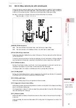
G69. Dri
lling
c
a
nned cycl
e w
ith var
iable peck
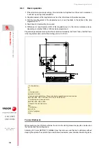
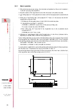
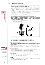
The first drilling penetration is done in G07 or G50 depending on the value assigned to the parameter
of the longitudinal axis "INPOSW2 (P51)" and to parameter "INPOSW1 (P19)". This is important
to join a drilling operation with another one in multiple drilling so the tool path is faster and smoother.
If INPOSW2 < INPOSW1 in G07 (square corner).
If INPOSW2 >= INPOSW1 in G50 (controlled round corner).
If a scaling factor is applied to this cycle, it should be borne in mind that this scaling factor will only
affect the reference plane coordinates and drilling depth.
Therefore, and due to the fact that parameter "D" is not affected by the scaling factor, the surface
coordinate of the part will not be proportional to the programmed cycle.
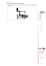
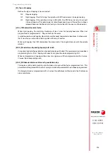
Tool withdrawal
While machining, the CNC lets withdraw the tool to the starting plane stopping the spindle when
the tool reaches the starting plane.
Activating PLC mark RETRACYC (M5065) stops the main axis and the tool is withdrawn without
stopping the spindle. The spindle stops when the tool is retracted, once it reaches the starting plane.
Options after tool withdrawal
Once the tool has been retracted, the user will have the following options:
• Finish the hole.
• Go to the next hole.
• Go into tool inspection.
After this, the CNC will display the following message:
"To end the cycle, press START to skip to the next SKIPCYCL".
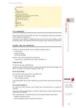
Finish the hole:
To finish the hole, press the [START] key.
It goes down in G0 with spindle running to 1 mm before the coordinate where the hole stopped. From
then on, it continues at the F and S programmed in the cycle.
Go to the next hole:
To go to the next hole, activate the PLC mark SKIPCYCL.
The CNC will display the following message:
"Press [START] to continue".
Pressing the [START] key, the CNC considers the cycle to be finished and continues with the next
block.
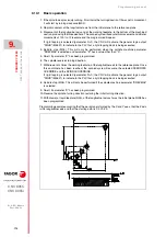
Programming example assuming that the work plane is formed by the X and Y axes, that the
Z axis is the longitudinal axis and that the starting point is X0 Y0 Z0:
; Tool selection.
T1
M6
; Starting point.
G0 G90 X0 Y0 Z0
; Canned cycle definition.
G69 G98 G91 X100 Y25 Z-98 I-52 B12 C2 D2 H5 J2 K150 L3 R0.8 F100 S500 M8
; Cancels the canned cycle.
G80
; Positioning.
G90 X0 Y0
; End of program.
M30
Summary of Contents for 8055 EN
Page 1: ...CNC 8055 M EN Programming manual Ref 1711 Soft V02 2x...
Page 8: ...8 Programming manual CNC 8055 CNC 8055i SOFT V02 2X...
Page 12: ...12 CNC 8055 CNC 8055i Declaration of conformity and Warranty conditions...
Page 16: ...16 CNC 8055 CNC 8055i Version history...
Page 22: ...22 CNC 8055 CNC 8055i Returning conditions...
Page 24: ...24 CNC 8055 CNC 8055i Additional notes...
Page 26: ...26 CNC 8055 CNC 8055i Fagor documentation...
Page 448: ......
Page 464: ...464 Programming manual CNC 8055 CNC 8055i D M EN MODELS SOFT V02 2X Key code...
Page 466: ...466 Programming manual CNC 8055 CNC 8055i D M EN MODELS SOFT V02 2X Key code MC operator panel...
Page 467: ...Programming manual CNC 8055 CNC 8055i D M EN MODELS SOFT V02 2X 467 Key code...
Page 468: ...468 Programming manual CNC 8055 CNC 8055i D M EN MODELS SOFT V02 2X Key code...
Page 471: ...Programming manual CNC 8055 CNC 8055i D M EN MODELS SOFT V02 2X 471 Key code 11 LCD Monitor...
Page 472: ...472 Programming manual CNC 8055 CNC 8055i D M EN MODELS SOFT V02 2X Key code...
Page 478: ...478 Programming manual CNC 8055 CNC 8055i F M EN MODELS SOFT V02 2X Maintenance...
Page 479: ...Programming manual CNC 8055 CNC 8055i F SOFT V02 2X 479...
Page 480: ...480 Programming manual CNC 8055 CNC 8055i F SOFT V02 2X...
Page 481: ......


