·334·
Programming manual
CNC 8055
CNC 8055i
12.
PROBING
·M· & ·EN· M
ODELS
S
OFT
: V02.2
X
PROBE 12
. Table
to
p
p
robe
cal
ibratio
n
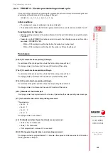
[ V±5.5 ] Approximate Y axis coordinate of the most positive side of the probe
Approximate coordinate of the most positive side of the probe, along the ordinate axis. If not
programmed, it will assume the value of general machine parameter PRBYMAX (P43).
[ Z±5.5 ] Approximate Z axis coordinate of the least positive side of the probe
Approximate coordinate of the least positive side of the probe, along the Z axis. If not programmed,
it will assume the value of general machine parameter PRBZMIN (P44).
[ W±5.5 ] Approximate Z axis coordinate of the most positive side of the probe
Approximate coordinate of the most positive side of the probe, along the Z axis. If not programmed,
it will assume the value of general machine parameter PRBZMAX (P45).
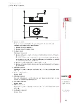
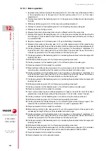
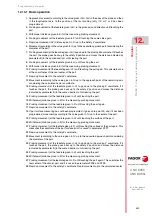
Operation
1.
Spindle orientation at 0º (only for double calibration).
2.
Initial positioning movement to the initial approach coordinates.
3.
Probing movement (at the feedrate given in H) up to the Z probing coordinate (in the middle of
the probe). If it touches the part, the CNC issues the corresponding error.
4.
Probing movement (at the feedrate given in H), in the X axis and in the given direction until
touching the first side.
5.
Rapid withdrawal along the X axis (distance given in E) for the measuring probing move.
6.
Probing movement (at the feedrate given in F) until touching the same side again.
7.
Rapid withdrawal up to the X approach coordinate.
8.
Rapid withdrawal in Z up to the Z approach coordinate.
9.
Rapid X axis movement up to the approach point of the other side considering the theoretical
length of the probe on the X axis and the value of parameter B.
10.
Probing movement (at the feedrate given in H) to go down to the probing Z coordinate. If it
touches the probe, it goes back up to the approach coordinate and moves the safety distance
indicated in the same direction. This movement is repeated until clearing the probe.
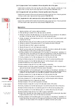
11.
Probing movement on X (at the feedrate given in H) until touching that side.
12.
Rapid withdrawal along the X axis (distance given in E) for the measuring probing move.
13.
Probing movement on X (at the feedrate given in F) until touching the same side again.
14.
Rapid withdrawal up to the X approach coordinate.
15.
Rapid movement along the Z axis up to the Z approach coordinate.
16.
Rapid movement up to the approach coordinate to the minimum Y side of the probe (the X
approach coordinate corresponds to the real center of the probe).
17.
Probing movement (at the feedrate given in H) to go down to the probing Z coordinate. If it
touches the probe, it goes back up to the approach coordinate and moves the safety distance
indicated in the same direction. This movement is repeated until clearing the probe.
18.
Probing movement on Y (at the feedrate given in H) until touching that side.
19.
Rapid withdrawal along the Y axis (distance given in E) for the measuring probing move.
20.
Probing movement on Y (at the feedrate given in F) until touching the same side again.
21.
Rapid withdrawal up to the Y approach coordinate.
22.
Rapid movement in Z up to the Z approach coordinate.
23.
Rapid movement along the Y axis up to the theoretical center of the probe.
24.
Probing movement on Z (at the feedrate given in H) until touching the Z side of the probe.
25.
Rapid withdrawal along the Z axis (distance given in E) for the measuring probing move.
26.
Probing movement on Z (at the feedrate given in F) until touching the same side again.
27.
Rapid movement along the Z axis up to the Z approach coordinate.
28.
Rapid Y axis movement up to the approach point of the other side considering the theoretical
length of the probe on the Y axis and the value of parameter B.
29.
Probing movement (at the feedrate given in H) to go down to the probing Z coordinate. If it
touches the probe, it goes back up to the approach coordinate and moves the safety distance
indicated in the same direction. This movement is repeated until clearing the probe.
Summary of Contents for 8055 EN
Page 1: ...CNC 8055 M EN Programming manual Ref 1711 Soft V02 2x...
Page 8: ...8 Programming manual CNC 8055 CNC 8055i SOFT V02 2X...
Page 12: ...12 CNC 8055 CNC 8055i Declaration of conformity and Warranty conditions...
Page 16: ...16 CNC 8055 CNC 8055i Version history...
Page 22: ...22 CNC 8055 CNC 8055i Returning conditions...
Page 24: ...24 CNC 8055 CNC 8055i Additional notes...
Page 26: ...26 CNC 8055 CNC 8055i Fagor documentation...
Page 448: ......
Page 464: ...464 Programming manual CNC 8055 CNC 8055i D M EN MODELS SOFT V02 2X Key code...
Page 466: ...466 Programming manual CNC 8055 CNC 8055i D M EN MODELS SOFT V02 2X Key code MC operator panel...
Page 467: ...Programming manual CNC 8055 CNC 8055i D M EN MODELS SOFT V02 2X 467 Key code...
Page 468: ...468 Programming manual CNC 8055 CNC 8055i D M EN MODELS SOFT V02 2X Key code...
Page 471: ...Programming manual CNC 8055 CNC 8055i D M EN MODELS SOFT V02 2X 471 Key code 11 LCD Monitor...
Page 472: ...472 Programming manual CNC 8055 CNC 8055i D M EN MODELS SOFT V02 2X Key code...
Page 478: ...478 Programming manual CNC 8055 CNC 8055i F M EN MODELS SOFT V02 2X Maintenance...
Page 479: ...Programming manual CNC 8055 CNC 8055i F SOFT V02 2X 479...
Page 480: ...480 Programming manual CNC 8055 CNC 8055i F SOFT V02 2X...
Page 481: ......

