01-2019 5505 00
81
BOARD FUNCTIONS
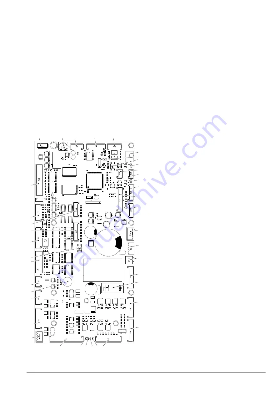
CPU BOARD
The board is arranged on the sliding shelf
and intended to manage the machine op-
eration.
The board has got a Flash EPROM, which
means that it can be electrically re-written
(e.g. for a software update).
Some leds on the board supply the follow-
ing information
-DL1: yellow led, which means 5V applied
-DL2: red led on, which means that the
board has been reset
-DL3: green led, on during the operation of
the board
-DL4: green led, which means 24V applied
1
2
3
4
5
6
8
9
10
11
12
13
14
15
16
17
18
19
20
21
22
23
24
25
26
27
28
29
30
31
32
33
34
35
36
37
38
39
40
7
Fig. 51
1. (P21A) safety micro connector
2. (J3_558) not used
3. (J11_558) not used
4. buzzer
5. (J4) temperature probe
6. (J5) validator connection
7. (SW2) not used
8. (J6) direct selection keyboard (if available)
9. (J16) touch screen supply
10. (J18) Upkey
11. (J7) not used
12. (J8) not used
13. (J22) not used
14. (J21) not used
15. (J9) not used
16. (J10) RS232 serial connector
17. (J12) EXE/BDV payments
18. (J11) MDB payments
19. (JP1) watchdog jumper (closed)
20. (SW1) not used
21. (JP2) canbus jumper (open)
22. (J13)
canbus
23. (J14)
canbus
24. (JP3) not used
25. (J15) display supply
26. (J13_558) photocells
27. (J17) not used
28. (P4A1) not used
29. (J20) 24V EXE supply
30. (J19) not used
31. (J2) compartment lock and lighted path led
32. Safety relay
33. (J15_558) softvend
34. (J14_558) motor-driven compartment,
compartment lighting
35. (J3) compressor, glassfront heating element,
external programming key
36. (DL4) green led “24V applied”
37. (DL3) green led “run”
38. (DL2) red led “reset”
39. (DL1) yellow led “5V applied”
40. (J1) tray motors


