590SP Digital Product Manual
App. M - 19
Appendix M Special Blocks and Application Notes
M
CLOSED-LOOP SPEED PROGRAMMED WINDER (SPW)
A speed programmed winder, SPW, provides closed-loop center winder control. It programs the motor speed using
either loadcell or dancer feedback for tension control.
This configuration provides standard features used in center winder applications including: diameter calculation with
memory and preset, tension and taper, PID for loadcell tension or dancer position control, and over/under winding. It
can control unwinds or rewinds for single-spindle and turret winders. The configuration uses four function blocks in
the SPECIAL BLOCKS; DIAMETER CALC., TAPER CALC., SETPOINT SUM 2, and PID.
Description
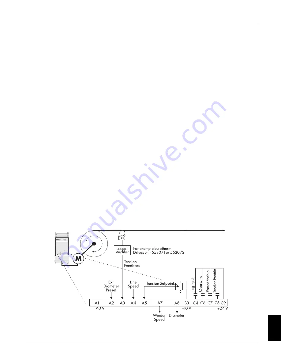
Figures M.15 and M.16 show typical SPW applications. SPW applications use closed-loop trim to modify the winder
speed. Line speed is conditioned in RAMPS before being combined with the tension trim in SETPOINT SUM 2. The
result, SPT. SUM OUTPUT, is scaled by DIAMETER and MIN DIAMETER in SETPOINT SUM 1 to produce the
speed demand.
TAPER CALC.:: TOT. TENS DEMAND uses inputs to terminals A5, TENSION SETPOINT, and A6, TAPER SET-
POINT, to produce a diameter compensated tension demand. It produces either the tension setpoint for loadcell appli-
cations or dancer loading signal for dancer applications. TAPER SETPOINT is not used in unwind applications.
Terminal C6, OVERWIND, switches the speed demand sign for overwinding or underwinding. The winder can change
directions by changing the LINE SPEED signal at terminal A4 to the opposite sign.
Loadcell Applications
In loadcell applications, the controller attempts to keep the tension at the loadcell constant by varying the winder
speed. The setting at terminal A5, TENSION SETPOINT, sets the desired loadcell tension. In TAPER CALC., the ten-
sion setpoint is compensated for diameter and taper. The output, TOT. TENS DEMAND, is the PID setpoint signal at
PID:: INPUT 1.
PID compares the setpoint, PID:: INPUT 1, with TENSION FEEDBACK from terminal A3. The output, PID OUT-
PUT, is the tension loop trim used in SETPOINT SUM 2.
Figure M.14 - Unwind SPW Application with Loadcell Feedback
Summary of Contents for 590SP
Page 2: ......
Page 16: ...1 4 590SP Digital Product Manual 1 Chapter 1 Introduction ...
Page 18: ...2 2 2 590SP Digital Product Manual Chapter 2 Identification ...
Page 31: ...Figure 3 3 Wiring Circuit Diagram for 590SP Digital Drive ...
Page 41: ...4 10 4 590SP Digital Product Manual Chapter 4 Start up and Adjustment DIGTIAL ...
Page 67: ...6 590SP Digital Product Manual Chapter 6 Service and Maintenance 6 6 ...
Page 89: ...B Appendix B Using the Man Machine Interface App B 4 590SP Digitial Product Manual ...
Page 125: ...Appendix C Setup Parameters 590 DRV Digital DC Drive Product Manual App C 36 C ...
Page 149: ...Appendix D I O Configuration System Menu App D 24 D 590SP Digital DC Drive Product Manual ...
Page 150: ...t t t t Figure D 20 590SP Digital Software Block Diagram ...
Page 160: ...590SP Digital Product Manual App E 10 E Appendix E MMI Parameter List ...
Page 168: ...Appendix G RS232 System Port P3 590SP Digital Product Manual App G 6 G ...
Page 194: ...Appendix H RS422 Communications Ports P1 P2 590SP Digital Product Manual App H 26 H ...
Page 220: ...App L 6 590SP Digital Product Manual L Appendix L 590SP DRV Option ...
Page 221: ...Figure L 5 Wiring Circuit Diagram for 590SP Digital DRV Drive ...
Page 259: ...590SP Digital Product Manual App M 38 Appendix M Special Blocks and Application Notes M ...


