Appendix C Setup Parameters
590 DRV Digital DC Drive Product Manual
App. C - 14
C
STOP RATES
The STOP RATES parameters are used when stopping using a normal stop or a
program stop.
Inputs and Outputs
Inputs are SPEED SETPOINT and SPEED FEEDBACK from the speed loop, RUN
from terminal C3, and PROGRAM STOP from terminal B8. The outputs are SPEED
DEMAND to the speed loop, PROG STOP I LIMIT to the current loop, and signals to
the coast stop and drive enable logic.
Description
A normal stop occurs when the RUN signal is removed from terminal C3. It ramps the
speed demand to zero at a rate set by STOP TIME. Non-regenerative drives will stop
no faster than the coast stop rate. Regenerative drives use STOP TIME to set the
duration of the stop. After the stop, the contactor de-energizes and the drive disables.
The STOP LIMIT timer starts when C3 goes to zero volts. If the drive speed has not
reached STOP ZERO SPEED within the STOP LIMIT time, the contactor de-ener-
gizes and the drive disables.
During normal stops, CONTACTOR DELAY delays de-energizing the contactor after
the motor reaches zero speed. When STOP ZERO SPEED is set above 0.25%, the
drive disables during the contactor delay. Below 0.25%, the drive disables after the
contactor delay. This is useful when using the jog function to prevent multiple
operations of the contactor. CONTACTOR DELAY is overridden when terminal C5
is at zero volts.
PROGRAM STOP provides a controlled fast stop using regenerative drives. The stop time is set by PROGRAM
STOP TIME. The timer starts once terminal B8 goes to zero volts. When the drive reaches STOP ZERO SPEED, the
contactor de-energizes and the drive disables. PROGRAM STOP LIMIT sets the maximum time the program stop can
take before the contactor de-energizes and the drive disables.
PROG STOP I LIM sets the current limit in the current loop during a program stop. Other current limits can override
it.
Parameters
Tag Parameter
Description
Range
Default
27
STOP TIME
Time to reach zero speed when performing a normal stop.
0.1 to 600.0 Secs
10.0 Secs
217
STOP LIMIT
The maximum time a controlled stop can take in a
0.0 to 600.0 Secs
60.0 Secs
normal stop before the drive will coast stop.
302
CONTACTOR DELAY The time the contactor stays energized after the STOP
0.1 to 600.0 Secs
1.0 Secs
ZERO SPEED limit is reached.
26
PROG STOP TIME
Time to reach zero speed when performing a program
0.1 to 600.0 Secs
0.1 Secs
stop.
216
PROG STOP LIMIT
The maximum time a program stop can take before the
0.0 to 600.0 Secs
60.0 Secs
contactor is de-energized and the drive is disabled.
91
PROG STOP I LIM
Current limit when performing a program stop.
0.00 to 200.00%
100.00%
29
STOP ZERO SPEED
Threshold where the CONTACTOR DELAY timer starts.
0.00 to 100.00%
2.00%
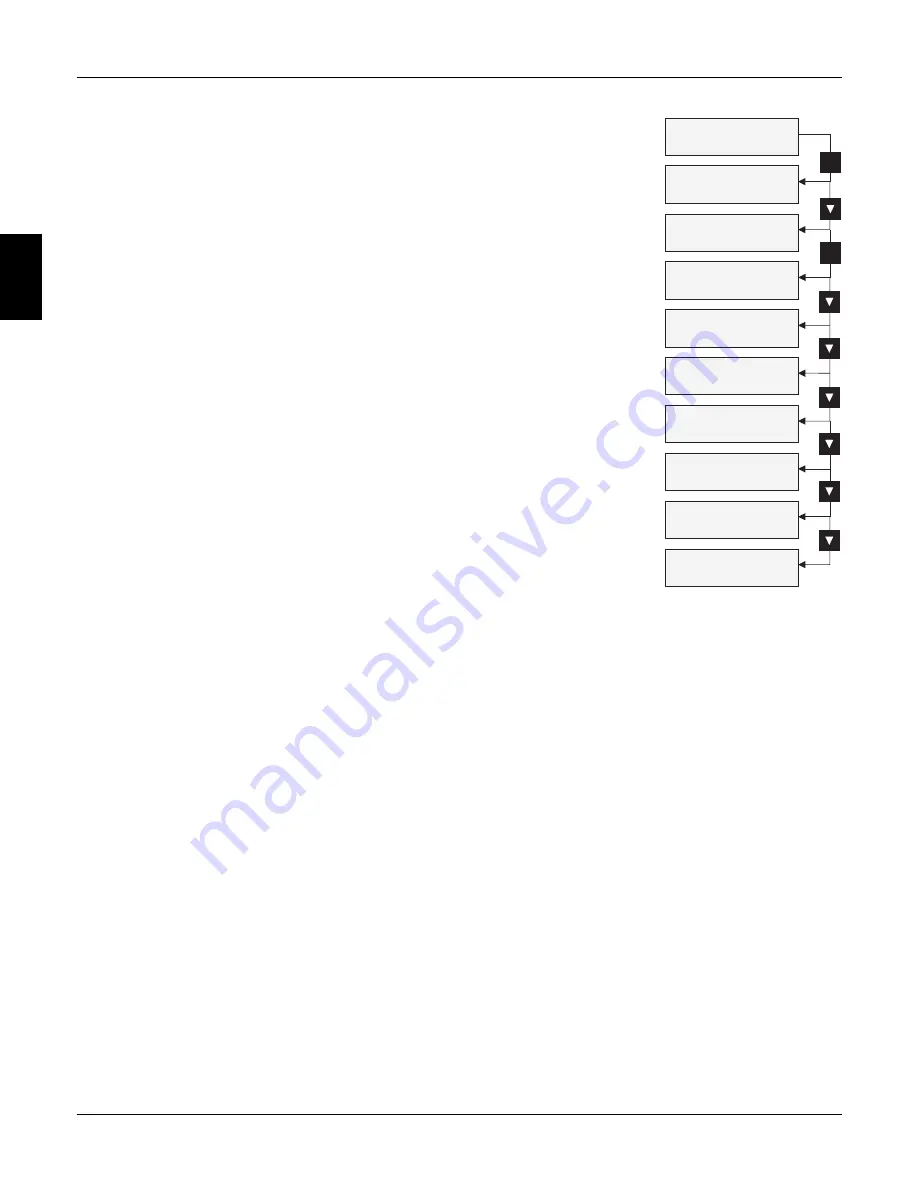
590SP DC DRIVE
MENU LEVEL
MENU LEVEL
DIAGNOSTICS
MENU LEVEL
SETUP PARAMETERS
SETUP PARAMETERS
RAMPS
SETUP PARAMETERS
AUX I/O
SETUP PARAMETERS
JOG/SLACK
SETUP PARAMETERS
SETUP PARAMETERS
RAISE/LOWER
SPECIAL BLOCKS
SETUP PARAMETERS
SETUP PARAMETERS
CURRENT PROFILE
STOP RATES
M
M
Summary of Contents for 590SP
Page 2: ......
Page 16: ...1 4 590SP Digital Product Manual 1 Chapter 1 Introduction ...
Page 18: ...2 2 2 590SP Digital Product Manual Chapter 2 Identification ...
Page 31: ...Figure 3 3 Wiring Circuit Diagram for 590SP Digital Drive ...
Page 41: ...4 10 4 590SP Digital Product Manual Chapter 4 Start up and Adjustment DIGTIAL ...
Page 67: ...6 590SP Digital Product Manual Chapter 6 Service and Maintenance 6 6 ...
Page 89: ...B Appendix B Using the Man Machine Interface App B 4 590SP Digitial Product Manual ...
Page 125: ...Appendix C Setup Parameters 590 DRV Digital DC Drive Product Manual App C 36 C ...
Page 149: ...Appendix D I O Configuration System Menu App D 24 D 590SP Digital DC Drive Product Manual ...
Page 150: ...t t t t Figure D 20 590SP Digital Software Block Diagram ...
Page 160: ...590SP Digital Product Manual App E 10 E Appendix E MMI Parameter List ...
Page 168: ...Appendix G RS232 System Port P3 590SP Digital Product Manual App G 6 G ...
Page 194: ...Appendix H RS422 Communications Ports P1 P2 590SP Digital Product Manual App H 26 H ...
Page 220: ...App L 6 590SP Digital Product Manual L Appendix L 590SP DRV Option ...
Page 221: ...Figure L 5 Wiring Circuit Diagram for 590SP Digital DRV Drive ...
Page 259: ...590SP Digital Product Manual App M 38 Appendix M Special Blocks and Application Notes M ...


