Appendix H RS422 Communications (Ports P1 & P2)
590SP Digital Product Manual
App. H - 24
H
Coil
Coil
APPLICATION NOTES
It is possible to make serial communications operate without following all the recommendations in this section;
however, the recommendations will promote greater reliability.
Host Computer
If possible, avoid using host computers which take their transmitter to a high impedance state (tri-state) when idling.
If it is unavoidable, then it is essential to use properly screened cable, such as suggested below.
Terminations
The drive farthest from the host computer should have a terminating resistor. The terminating resistor should be
changed to match the characteristic impedance of the cable, typically 100 to 150
W
. The resistors on all other drives
should be removed.
Cable Routing
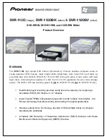
Daisy chain one drive to the next; avoid spurs. Connect the host computer at one end of the daisy-chain. The host
computer's TX+ terminal connects to all the RX+ terminals along the daisy chain. Its RX+ terminal connects to all the
drive's TX+ terminals in the chain. This same pattern is followed for the TX- and RX- terminals. See Figure
H.6 for an illustration of the wiring scheme.
Grounding
Connect the screens of both pairs of wires to ground at the host computer. If possible, connect the host computer's
transmitter/receiver zero volts reference to ground.
Figure H.6 - Serial Link Connections
Summary of Contents for 590SP
Page 2: ......
Page 16: ...1 4 590SP Digital Product Manual 1 Chapter 1 Introduction ...
Page 18: ...2 2 2 590SP Digital Product Manual Chapter 2 Identification ...
Page 31: ...Figure 3 3 Wiring Circuit Diagram for 590SP Digital Drive ...
Page 41: ...4 10 4 590SP Digital Product Manual Chapter 4 Start up and Adjustment DIGTIAL ...
Page 67: ...6 590SP Digital Product Manual Chapter 6 Service and Maintenance 6 6 ...
Page 89: ...B Appendix B Using the Man Machine Interface App B 4 590SP Digitial Product Manual ...
Page 125: ...Appendix C Setup Parameters 590 DRV Digital DC Drive Product Manual App C 36 C ...
Page 149: ...Appendix D I O Configuration System Menu App D 24 D 590SP Digital DC Drive Product Manual ...
Page 150: ...t t t t Figure D 20 590SP Digital Software Block Diagram ...
Page 160: ...590SP Digital Product Manual App E 10 E Appendix E MMI Parameter List ...
Page 168: ...Appendix G RS232 System Port P3 590SP Digital Product Manual App G 6 G ...
Page 194: ...Appendix H RS422 Communications Ports P1 P2 590SP Digital Product Manual App H 26 H ...
Page 220: ...App L 6 590SP Digital Product Manual L Appendix L 590SP DRV Option ...
Page 221: ...Figure L 5 Wiring Circuit Diagram for 590SP Digital DRV Drive ...
Page 259: ...590SP Digital Product Manual App M 38 Appendix M Special Blocks and Application Notes M ...