


Chapter 3 Installation and Wiring
590SP Digital Product Manual
3 - 6
3
▼
Drive must
Control Contactor
Coil
DC Contactor
Wiring
G
H
AC Contactor
Wiring
I
Dynamic Brake
Contactor
Interlock
Contactor to Zero
Speed
Jumper C5 to
+24 VDC
(terminal C9)
Switch C5 to +24
VDC (C9) thru
n/o contactor
auxiliary
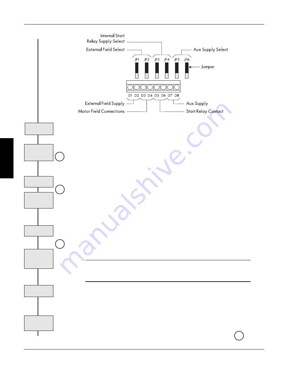
Figure 3.6- Auxiliary Control Jumpers
Check Jumpers
JP5 and JP6
(line). Move jumpers JP5 and JP6 from positions 2 and 3 to positions 1 and 2 to power the control
transformer externally. The supply is protected by a 1.6 amp fuse.
Motor Isolation
Isolate the motor from power by either breaking the controller input supply with an AC contactor or
the output power with a DC contactor. The 590SP Digital drive must control this contactor to ensure
that current flow is never interrupted while the thyristors are firing.
AC Contactor Wiring
AC contactor wiring is shown in the upper right portion of the wiring diagram in Figure 3.3. Use a
two-pole, normally-opened contactor rated to handle the AC voltage and supply current. Wire the
contactor poles between branch AC circuit protection and the supply input terminals (L1 and L2).
Permanently enable the drive by jumpering terminal C5 (ENABLE) to terminal C9 (+24 VDC).
Always isolate input power to the drive by dropping out the AC contactor power before servicing
the equipment.
NOTE. The control supply must be supplied externally when using an AC contactor.
Connect it as described above in Control Power Wiring.
DC Contactor Wiring
Wire a suitably rated DC contactor between the drive output terminals (A+ and A-) and the motor
armature. Connect terminal C5 (ENABLE) to terminal C9 (+24 VDC) through a normally opened
auxiliary of the main contactor. This keeps the drive disabled until the main contactor closes, and
disables the drive when the contactor opens.
WARNING!
When isolating the armature using a DC contactor, the field remains powered while
the contactor is de-energized.
Dynamic Braking
The DC contactor wiring schematic in Figure 3.3 shows wiring for an optional dynamic braking
application. Dynamic braking requires a DC contactor with an additional normally closed pole rated
to carry full load current upon closing.
NOTE. Dynamic brake contactor poles are rated to make, but not interrupt DC motor
current. To avoid damaging the normally closed contact, interlock the drive's zero
speed output signal to the drive start logic to prevent the drive from restarting until the
motor has reached standstill. This zero speed interlock relay logic is shown at in
Figure 3.3.
J
1
2
3
▼
Summary of Contents for 590SP
Page 2: ......
Page 16: ...1 4 590SP Digital Product Manual 1 Chapter 1 Introduction ...
Page 18: ...2 2 2 590SP Digital Product Manual Chapter 2 Identification ...
Page 31: ...Figure 3 3 Wiring Circuit Diagram for 590SP Digital Drive ...
Page 41: ...4 10 4 590SP Digital Product Manual Chapter 4 Start up and Adjustment DIGTIAL ...
Page 67: ...6 590SP Digital Product Manual Chapter 6 Service and Maintenance 6 6 ...
Page 89: ...B Appendix B Using the Man Machine Interface App B 4 590SP Digitial Product Manual ...
Page 125: ...Appendix C Setup Parameters 590 DRV Digital DC Drive Product Manual App C 36 C ...
Page 149: ...Appendix D I O Configuration System Menu App D 24 D 590SP Digital DC Drive Product Manual ...
Page 150: ...t t t t Figure D 20 590SP Digital Software Block Diagram ...
Page 160: ...590SP Digital Product Manual App E 10 E Appendix E MMI Parameter List ...
Page 168: ...Appendix G RS232 System Port P3 590SP Digital Product Manual App G 6 G ...
Page 194: ...Appendix H RS422 Communications Ports P1 P2 590SP Digital Product Manual App H 26 H ...
Page 220: ...App L 6 590SP Digital Product Manual L Appendix L 590SP DRV Option ...
Page 221: ...Figure L 5 Wiring Circuit Diagram for 590SP Digital DRV Drive ...
Page 259: ...590SP Digital Product Manual App M 38 Appendix M Special Blocks and Application Notes M ...


