


4 - 8
4
590SP Digital Product Manual
Chapter 4 Start-up and Adjustment
DIGTIAL
Figure 4.1 - Armature Current
Waveform
OTHER PARAMETERS
Other parameters, for example ramp rates, may be important for the process. Different ramp rates are available for
various conditions:
Condition
Parameter Name
Menu
Speed Setpoint Change
RAMP ACCEL TIME and RAMP DECEL TIME
RAMPS
Jog Acceleration/Deceleration
RAMP RATE
JOG/SLACK
Controlled Stop Deceleration
STOP TIME
STOP RATES
Fast Stop Deceleration
PROGRAM STOP TIME
STOP RATES
Electronic MOP Control
INCREASE RATE and DECREASE RATE
RAISE/LOWER
Appendix C fully discusses the functionality and scaling of all drive parameters.
RECORDING PARAMETERS
It is important to have a hard copy of your drive parameters. This copy might consist of writing down the information
on a chart, saving the parameters to a computer disk, or printing the parameters using an external computer. The
parameter list in Appendix C has two empty columns for manually recording the drive parameters.
To save the parameters as either a hexadecimal ASCII file or as a text file ready for printing, connect a computer to the
P3 serial port. Use a telecommunications program, such as Procomm™, Windows Terminal™, or other terminal emula-
tion programs. Refer to "Using Microsoft® Windows™ to Document and Clone 590 Digital Drives" (HA352155) for
Turn integral
defeat OFF
Adjust I Gain
▼
Set INPUT 3 (A4)
= +5 VDC
Monitor Response
1. Connect terminal B3 (+10 VDC) through a switch to terminal A3. This will provide the step change
input for verifying speed loop performance.
2. Calibrate terminal A3 for 10% output by setting SETUP
PARAMETERS:: SPEED LOOP:: SETPOINTS::
RATIO 2 (A3) to 0.1000.
3. Set SETUP PARAMETERS:: SPEED LOOP:: INT.
DEFEAT to ON. This disables the integral gain.
4. Run the motor at a typical operating speed through the
speed ramp input, terminal A4. The speed should not
exceed 50 percent.
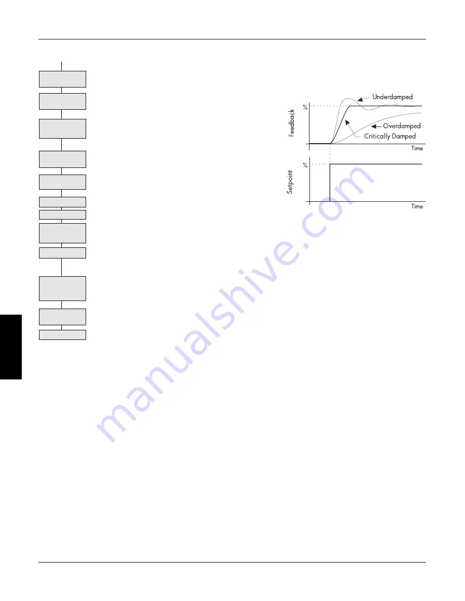
5. Check the speed loop performance by making step
changes using the switch at terminal A3. Increase
SETUP PARAMETERS:: SPEED LOOP:: PROP.
GAIN until the response is critically damped as illus-
trated above.
6. Once stable proportional control is attained, set SETUP
PARAMETERS:: SPEED LOOP:: INT. DEFEAT to
OFF.
7. Check the speed loop performance by making step changes using the switch at terminal A3. Reduce
SETUP PARAMETERS:: SPEED LOOP:: INT. TIME CONST until the response is critically damped.
NOTE. The default value for INT. TIME CONST is 0.5 seconds. That value may be too small
for large inertia loads and cause the system to be unstable from the start.
8. Stop the drive and remove the switched signal from terminal A3.
9. Reset the calibration for terminal A3 back to 100% by setting SYSTEM:: CONFIGURE I/O:: ANA-
LOG INPUTS:: ANIN 2 (A3) to 1.0000, then run normally.
10. Save parameters:
10 VDC
to A3
Adjust P Gain
Apply +10 VDC to
A3 thru Switch
Set A3 (INPUT 2
CAL) = 0.1000
Set Integral defeat
ON
Stop Drive.
Remove Switched
+10 VDC at A3.
Save Parameters
Set A3 (INPUT 2
CAL) = 1.0000
Summary of Contents for 590SP
Page 2: ......
Page 16: ...1 4 590SP Digital Product Manual 1 Chapter 1 Introduction ...
Page 18: ...2 2 2 590SP Digital Product Manual Chapter 2 Identification ...
Page 31: ...Figure 3 3 Wiring Circuit Diagram for 590SP Digital Drive ...
Page 41: ...4 10 4 590SP Digital Product Manual Chapter 4 Start up and Adjustment DIGTIAL ...
Page 67: ...6 590SP Digital Product Manual Chapter 6 Service and Maintenance 6 6 ...
Page 89: ...B Appendix B Using the Man Machine Interface App B 4 590SP Digitial Product Manual ...
Page 125: ...Appendix C Setup Parameters 590 DRV Digital DC Drive Product Manual App C 36 C ...
Page 149: ...Appendix D I O Configuration System Menu App D 24 D 590SP Digital DC Drive Product Manual ...
Page 150: ...t t t t Figure D 20 590SP Digital Software Block Diagram ...
Page 160: ...590SP Digital Product Manual App E 10 E Appendix E MMI Parameter List ...
Page 168: ...Appendix G RS232 System Port P3 590SP Digital Product Manual App G 6 G ...
Page 194: ...Appendix H RS422 Communications Ports P1 P2 590SP Digital Product Manual App H 26 H ...
Page 220: ...App L 6 590SP Digital Product Manual L Appendix L 590SP DRV Option ...
Page 221: ...Figure L 5 Wiring Circuit Diagram for 590SP Digital DRV Drive ...
Page 259: ...590SP Digital Product Manual App M 38 Appendix M Special Blocks and Application Notes M ...


