
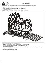


14
2
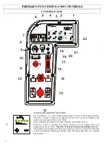
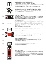
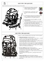
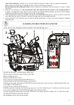
SUCTION FAN BUTTON
If the suction fan is switched off, this button can be used to turn it on, the squeegee
lowers and a green light indicator will come on.
If the suction fan is switched on, the light will start flashing, when this button is
pressed, but the suction function will remain active for a fixed period of time and
once lapsed the squeegee will lift and the suction function will come off.
The warning light will start flashing even when the machine is in reverse drive to
indicate that the squeegee is being raised from the floor.
The suction function may turn off automatically when the solution on the recovery
tank is too full. The machine is equipped with a float that switches off the function
when the tank reaches its maximum level. In case of prolonged idle time, the suction
fan will switch off automatically after 1 minute regardless of whether the squeegee
does not lift automatically from the floor for safety reasons, but must be lifted by
pressing the button
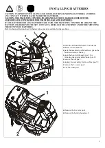
3
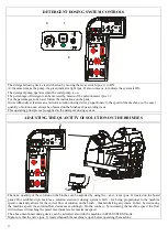
ECO-SYSTEM OPERATION BUTTON
Press this button to enable the ECO-SYSTEM.
The green light is on when the system is operating.
If the button is pressed and the led light does not come on, it means that the solution
level on the recovery tank is too low and therefore, the function cannot be enabled.
Continue to wash in “normal” mode until reaching the minimum level. However, it
is advisable to have enough solution in the recovery tank for better performance in
the ECO-SYSTEM mode.
If the level on the recovery tank goes below the minimum level required for the
ECO-SYSTEM function, all five led lights on the water metering unit will start
flashing and the brushes will stop operating.
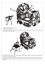
4
CHARGE BATTERY LEVEL INDICATOR AND DISPLAY
The charge level of the battery is displayed when the machine is switched on (100 –
90 – etc).
When the battery charge level reaches 20, the number on the display
starts blinking and the brush operation is disabled raising the plate, since a
protection device is triggered to prevent the battery from getting damaged,
however the suction and forward functions remain active.
At this point, the brush plate shall be raised and the floor shall be dried quickly.
Upon reaching level 10, the number on the display shall start blinking and the
suction function will also be disabled, the forward function will be the only active
function. Lift the squeegee, go to the tank drainage area and charge the batteries.
When 4 blinking dashes (----) appear on the display, the forward function will also
be disabled as the battery reaches a minimum discharging threshold. Therefore, the
machine must be pushed over to the tank drainage area and then pushed over to the
battery charging area.
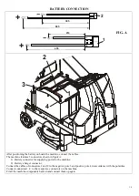
5
HOUR METER BUTTON
Hold down this button to display the operating hours of the machine.
6
HANDBRAKE ENGAGED RED INDICATOR LIGHT
When the LED is on and the buzzer buzzes, this means the handbrake is engaged.
Disengage the brake by means of the lever before starting to move the machine.
7
RED WARNING LIGHT: FORWARD GEAR MOTOR TEMPERATURE
If the temperature on the gear motor casing exceeds 75-85°C, the red warning light
will come on and the gear motor will stop operating, emitting a buzzing warning.


