Epson Research and Development
Page 23
Vancouver Design Center
Hardware Functional Specification
S1D13704
Issue Date: 01/02/08
X26A-A-001-04
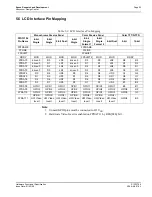
5.5 LCD Interface Pin Mapping
Note
1. Unused GPIO pins must be connected to IO V
DD
.
2. Hardware Video Invert is enabled on FPDAT11 by REG[02h] bit 1.
Table 5-3: LCD Interface Pin Mapping
S1D13704
Pin Name
Monochrome Passive Panel
Color Passive Panel
Color TFT/D-TFD
4-bit
Single
8-bit
Single
8-bit Dual
4-bit
Single
8-bit
Single
Format 1
8-bit
Single
Format 2
8-bit Dual
9-bit
12-bit
FPFRAME
FPFRAME
FPLINE
FPLINE
FPSHIFT
FPSHIFT
DRDY
MOD
MOD
MOD
MOD
FPSHIFT2
MOD
MOD
DRDY
FPDAT0
driven 0
D0
LD0
driven 0
D0
D0
LD0
R2
R3
FPDAT1
driven 0
D1
LD1
driven 0
D1
D1
LD1
R1
R2
FPDAT2
driven 0
D2
LD2
driven 0
D2
D2
LD2
R0
R1
FPDAT3
driven 0
D3
LD3
driven 0
D3
D3
LD3
G2
G3
FPDAT4
D0
D4
UD0
D0
D4
D4
UD0
G1
G2
FPDAT5
D1
D5
UD1
D1
D5
D5
UD1
G0
G1
FPDAT6
D2
D6
UD2
D2
D6
D6
UD2
B2
B3
FPDAT7
D3
D7
UD3
D3
D7
D7
UD3
B1
B2
FPDAT8
GPIO1
GPIO1
GPIO1
GPIO1
GPIO1
GPIO1
GPIO1
B0
B1
FPDAT9
GPIO2
GPIO2
GPIO2
GPIO2
GPIO2
GPIO2
GPIO2
GPIO2
R0
FPDAT10
GPIO3
GPIO3
GPIO3
GPIO3
GPIO3
GPIO3
GPIO3
GPIO3
G0
FPDAT11
GPIO4/
HW Video
Invert
GPIO4/
HW Video
Invert
GPIO4/
HW Video
Invert
GPIO4/
HW Video
Invert
GPIO4/
HW Video
Invert
GPIO4/
HW Video
Invert
GPIO4/
HW Video
Invert
GPIO4
B0
*

