

Page 72
Epson Research and Development
Vancouver Design Center
S1D13704
Hardware Functional Specification
X26A-A-001-04
Issue Date: 01/02/08
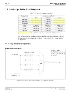
11 Look-Up Table Architecture
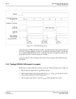
The following figures are intended to show the display data output path only. The CPU
R/W access to the individual Look-Up Tables is not affected by the various ‘banking’
configurations.
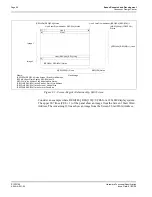
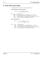
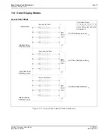
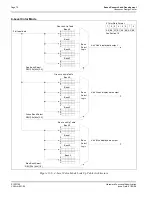
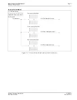
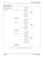
11.1 Gray Shade Display Modes
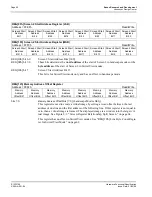
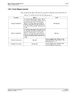
2-Level Gray Shade Mode
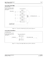
Figure 11-1: 2-Level Gray-Shade Mode Look-Up Table Architecture
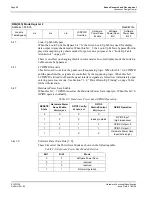
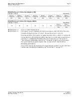
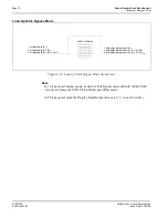
Table 11-1: Look-Up Table Configurations
Display Mode
4-bit wide Look-Up Table
RED
GREEN
BLUE
2-level gray
4 banks of 2
4-level gray
4 banks of 4
16-level gray
1 bank of 16
2 color
4 bank of 2
4 bank of 2
4 bank of 2
4 color
4 banks of 4
4 banks of 4
4 banks of 4
16 color
1 bank of 16
1 bank of 16
1 bank of 16
256 color
2 banks of 8
2 banks of 8
4 banks of 4
Indicates the Look-Up Table is not used for that display mode
0
1
1-bit pixel data
Green Bank Select
REG[16h] bits [3:2]
4-bit display data output
Bank
Select
Logic
2
3
6
7
4
5
Green Look-Up Table
7
6
5
4
3
2
1
0
A0 A1 A2 A3 A4 A5 A6 A7
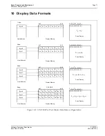
2 Gray Data Format:
See Section 10
*


