


Service Manual
Disassembly and Assembly
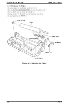
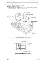
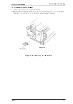
3.2.4.7 Removing the Carriage Assembly
1.
Remove the printer mechanism (see Section 3.2.4).
2. Remove the belt tension spring from the hook on the CR motor (see Section 3.2.4.2), and
remove the carriage assembly timing belt from the drive pulley.
3. Release the hook that attaches the head cable sheet to the base frame. Slide the cable to the left
and remove it.
4. Remove the printhead
from the base frame.
5. Remove the CR shaft grounding plate from the left side of the printer mechanism.
6. Rotate both sides of the parallelism adjustment bushing and remove them from the left and
right frame.
7. Remove the CR guide shaft assembly and the carriage assembly.
CR S
Adjustm
C a b l e H e a d
w
Figure 3-16. Removing the Carriage Assembly
3-15
Summary of Contents for LQ-300 - Impact Printer
Page 1: ...EPSON TERMINAL PRINTER LQ 300 SERVICE MANUAL EPSON ...
Page 5: ...REVISION SHEET Revision Issue Date Revision Page Rev A September 28 1994 1st issue f v 1 ...
Page 34: ...c f ...
Page 101: ...Maintenance LQ 300 Service Manual Figure 6 1 LQ 300 Lubrication Points 6 2 Rev A ...
Page 110: ... Figure A 6 C130 PSB PSE Component Layout ...
Page 112: ...Appendix LC MMS vbeMantd Q ix iyii t v Figure A 8 LQ 300 Exploded Diagram 2 A 12 Rev A ...
Page 119: ... f ...


