


Service Manual
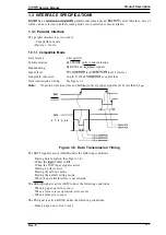
Product Description
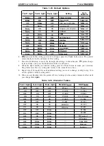
1.4.6 Selected Font
The combination of two
Font
LEDs (1 and2) is used to indicate the selected font.
To choose one of the seven internal fonts listed on the control panel, press the
Font
button.
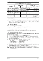
Table 1-17. Font Selection
Selected Font
Font 1
Font2 Light
Roman
On
On
Saris Serif
On
o f f
Courier
off
On
Prestiae
On
script
Blinking
off
Draft
On
Blinking
Draft condensed
off
off
1.4.7 Printer Initialization
There are three types of initialization:
power-on initialization, hardware initialization, and
software initialization.
1.4.7.1 Power-on Initialization
The power-on initialization is performed by turning the printer powered on. When the power-on
initialization is performed:
. The printer mechanism is initialized.
●
The
hardware initialization is performed.
1.4.7.2 Hardware Initialization
Hardware initialization is performed by:
. Turning on the printer.
. The falling edge of a negative pulse ora low signal on theparallel interface
When hardware initialization is performed:
●
Print data in the input buffer is cleared.
. Download character definitions are cleared.
. The printer’s settings areretumed to the defaults.
●
The
printer is set to the standby condition, if no fatal error occurs.
1.4.7.3
Software
Initialization
initialization is performed upon receipt of the control code ESC When software
initialization is performed:
●
Print characters in the buffer are not cleared.
. The printer setting is changed to the default, but download character definition is not cleared.
Rev.
1-19
Summary of Contents for LQ-300 - Impact Printer
Page 1: ...EPSON TERMINAL PRINTER LQ 300 SERVICE MANUAL EPSON ...
Page 5: ...REVISION SHEET Revision Issue Date Revision Page Rev A September 28 1994 1st issue f v 1 ...
Page 34: ...c f ...
Page 101: ...Maintenance LQ 300 Service Manual Figure 6 1 LQ 300 Lubrication Points 6 2 Rev A ...
Page 110: ... Figure A 6 C130 PSB PSE Component Layout ...
Page 112: ...Appendix LC MMS vbeMantd Q ix iyii t v Figure A 8 LQ 300 Exploded Diagram 2 A 12 Rev A ...
Page 119: ... f ...


