


Service Manual
Product Description
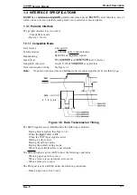
1.3.1.2 Reverse Mode
reverse mode supports
nibble mode, described in this section.
Transmission mode:
nibble mode
Signal level:
level 1 device
Adaptable connector:
36-pin 57-30360
or equivalent
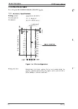
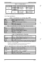
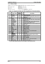
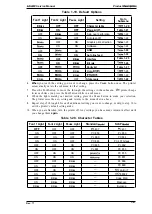
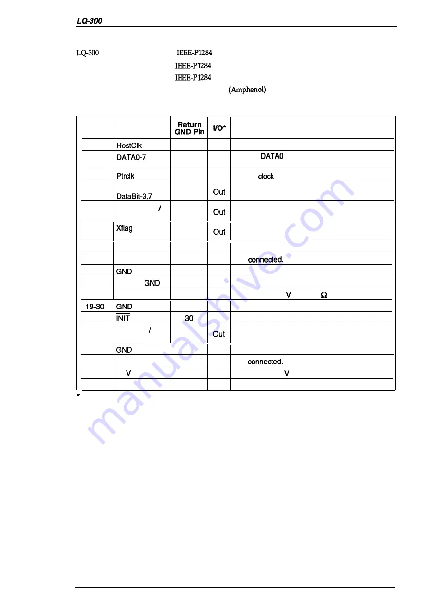
Table 1-14. Signal and Connector Pin Assignments for Parallel Interface
Pin No.
Signal Name
Description
1
19
In
Host clock signal.
2-9
20-27
In
Signals
through DATA7 represent data
bits O to 7.
10
28
out
Printer
signaL
11
PtrBusy /
29
Printer busy signal and reverse channel transfer
data bit 3 or 7.
12
AckDataReq
28
Acknowledge data request signal and reverse
DataBit-2,6
channel transfer data bit 2 or 6.
13
I
28
X-flag signal and reverse channel transfer data
DataBit-l,5
bit 1 or5.
14
HostBusy
30
In
Host busy signal.
15
NC
—
—
Not
16
.
—
Signal ground.
17
Chassis
—
—
Chassis ground.
18
Logic-H
—
o u t
Pulled up to +5 via 3.9K resistor.
—
—
Signal ground.
31
In
Not used.
32
DataAvail
29
Data available signal and reverse channel
DataBit-0,4
transfer bit O or 4.
33
—
—
Signal ground.
34
NC
—
—
Not
35
+5
—
o u t
Pulled up to +5 via 3.3K S2 resistor.
36
1284-Active
30
In
1284 active signal.
The l/O column indicates the direction of the signal as viewed from the printer.
Rev. A
1-13
Summary of Contents for LQ-300 - Impact Printer
Page 1: ...EPSON TERMINAL PRINTER LQ 300 SERVICE MANUAL EPSON ...
Page 5: ...REVISION SHEET Revision Issue Date Revision Page Rev A September 28 1994 1st issue f v 1 ...
Page 34: ...c f ...
Page 101: ...Maintenance LQ 300 Service Manual Figure 6 1 LQ 300 Lubrication Points 6 2 Rev A ...
Page 110: ... Figure A 6 C130 PSB PSE Component Layout ...
Page 112: ...Appendix LC MMS vbeMantd Q ix iyii t v Figure A 8 LQ 300 Exploded Diagram 2 A 12 Rev A ...
Page 119: ... f ...


