


Disassembly and Assembly
Service Manual
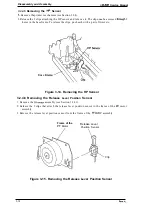
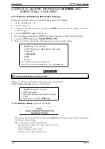
3.2.3.1
Removing the
MAIN Board Assembly
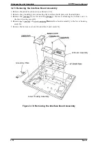
1. Remove the
assembly
MAIN board assembly.
2. Remove the
x8).
3. Remove the MAIN board assembly.
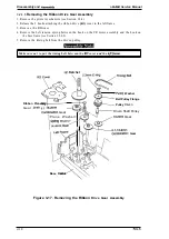
3.2.3.2
Removing the
Board Assembly
Remove the
for the
board assembly from connector CN2 on the MAIN board
assembly.
2. Remove
C
x 10) screw and 2 CB
C
x 8) screws.
3. Remove the
assembly.
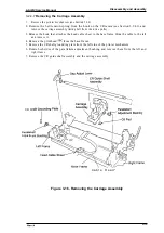
●
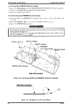
When replacing the MAIN board assembly, bend the LED lead wires parallel to the MAIN
board assembly
Figure 3-7).
●
The shield plate is easily bent; be
when tightening the screws that attach it to the
and
board assemblies.
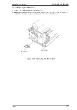
C(M3X1O)
P l a t e
\ ,
.
.
/
Board Assembly
MAIN Board Assembly
Figure 3-6. Removing MAIN and
Board Assemblies
MAIN Board Assembly
\
Figure 3-7. Bending the LED Lead
Wires
3-8
Summary of Contents for LQ-300 - Impact Printer
Page 1: ...EPSON TERMINAL PRINTER LQ 300 SERVICE MANUAL EPSON ...
Page 5: ...REVISION SHEET Revision Issue Date Revision Page Rev A September 28 1994 1st issue f v 1 ...
Page 34: ...c f ...
Page 101: ...Maintenance LQ 300 Service Manual Figure 6 1 LQ 300 Lubrication Points 6 2 Rev A ...
Page 110: ... Figure A 6 C130 PSB PSE Component Layout ...
Page 112: ...Appendix LC MMS vbeMantd Q ix iyii t v Figure A 8 LQ 300 Exploded Diagram 2 A 12 Rev A ...
Page 119: ... f ...


