


Service Manual
Operating Principles
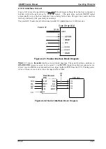
2.3.10 Interface Circuit
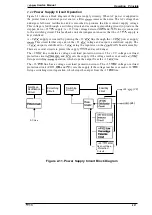
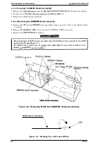
Figure 2-21 shows the parallel interface
block diagram. Data from the host computer is
latched within the gate array by STROBE signal.
The gate array outputs XBUSY signal
automatically to stop the host computer from sending further data. The gate array reads the data
latched periodically with generating an interrupt.
The parallel I/F conforms to bidirectional parallel I/F
level 1 nibble mode.
Parallel l/F
Gate
Array
127-134
DINO-7
39
- - - - -
:
13
12 ‘
- - - -
4
------ XPE
14
------ XERR
4
15
------ XSLCT
4
‘
- - -
”
-
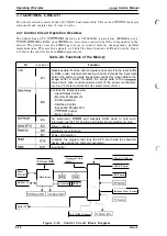
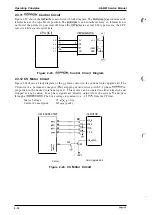
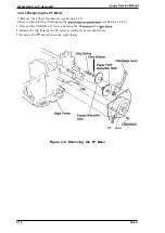
2-22 shows
Figure 2-21. Parallel Interface Block Diagram
the serial
interface circuit block diagram. The serial interface conforms to
is data received by the serial 1/0 of
block from the host computer via
driver/receiver
Data is transmitted to an input buffer in
from the CPU. Printing starts
when a CR code is received or when the input buffer is filled.
Driver/Receiver
Serial
TXD
. D1OUT
53
DTR
D21N
52
50
R1OUT
CTS
R21N
54
RST
CPU (lCl)
P33
P32
P30
P34
Figure 2-22. Serial Interface
Block Diagram
2-17
Summary of Contents for LQ-300 - Impact Printer
Page 1: ...EPSON TERMINAL PRINTER LQ 300 SERVICE MANUAL EPSON ...
Page 5: ...REVISION SHEET Revision Issue Date Revision Page Rev A September 28 1994 1st issue f v 1 ...
Page 34: ...c f ...
Page 101: ...Maintenance LQ 300 Service Manual Figure 6 1 LQ 300 Lubrication Points 6 2 Rev A ...
Page 110: ... Figure A 6 C130 PSB PSE Component Layout ...
Page 112: ...Appendix LC MMS vbeMantd Q ix iyii t v Figure A 8 LQ 300 Exploded Diagram 2 A 12 Rev A ...
Page 119: ... f ...


