The Memory Expansion Boards
3.
If desired, install additional memory chip sets to the optional
memory board as described earlier in this section.
Note:
This section shows the installation of the
2
MB memory
expansion board. The procedure is the same for the
2
MB or the
.5
MB board.
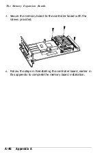
4. Locate mating connector CN5 on the controller board. Lower
the memory expansion board into position as shown below,
and carefully insert the connector on the board into the mating
connector.
Appendix A
A-45
Summary of Contents for EPL-7000
Page 1: ......
Page 2: ......
Page 280: ...HP Emulation Mode PcMultilingual Appendix B B 5 ...
Page 281: ...HP Emulation Mode ECMA94 Latin 1 Set B 6 Appendix B ...
Page 286: ...HP Emulation Mode HP IBM US Set Symbol Set ID 10U IBM US IBM DN Appendix B B 11 ...
Page 328: ......
Page 329: ......


