


Page 90
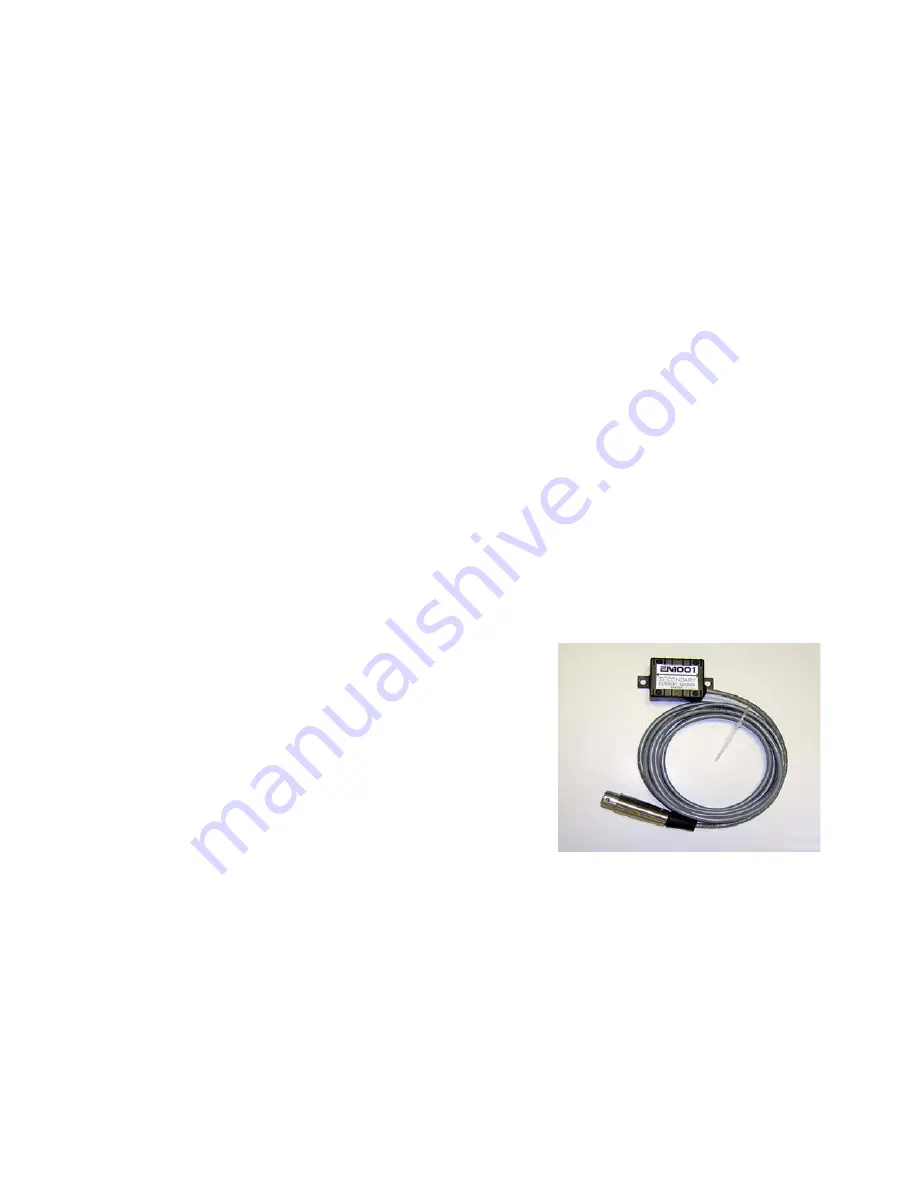
Figure 8.3.1 Hall-Effect Sensor
5. Before sequence initiation, select Percent Current using the SELECT push-button.
6. Make sample welds with chosen schedule to determine the proper welding transformer
tap switch setting . Weld time should be the recommended number of cycles for the
material being welded. Percent current should be high enough in order to achieve
desired secondary current. After end of weld and releasing initiation switch, current in
kA will be shown on DATA displays.
7. At this point press and hold ENTER push-button, on DATA displays [
=!0!Z!,!
] message
will appear. While ENTER is held, press SELECT push-button to store this
set
point
,
which represents correlation between phase shift percent and current in kA, in to
EEPROM memory of the Control.
8. After this, the Control can be reprogrammed back to one of the corresponding
compensation modes [
.!X!
] = 12, 14, 16, or 18.
Calibration of Current Display
9. Once Compensation Mode 12, 14, 16, or 18 is selected, the turns ratio needs to be
adjusted so that the displayed secondary current value matches the value displayed on
a weld analyzer or other equipment capable of displaying the secondary current.
a. Start with the [rA] =
8.3 CONSTANT CURRENT OPERATION WITH SECONDARY HALL
EFFECT BASED CURRENT TRANSDUCER
The EN1001 Control in constant current mode with a Secondary Hall-Effect Transducer as
current sensor beside
percent
mode, allows Range (Proportional)
kA
mode of operation. In
both cases, setup procedure for auto gain selection is required as described in Section 8.1.3.
Manual gain or range selection along with sensor positioning should be performed, as
described in Section 8.3.2, if setup is not possible. Choose and program one of the modes
from the Table 5.4.14 or Table 5.4.15, as described in sections 5.4.14 and 5.4.15.
8.3.1 AUTO RANGE OR PROPORTIONAL MODE WITH SETUP
In this mode, a learning type setup is required. This mode
should be used in percent mode with [
X!,!
]=00.99, or kA mode
with [
X!,!
] as maximum RMS secondary current entered at the
end of setup procedure.
1. Put the control in PROGRAM Mode.
2. Click SELECT until the DATA display shows [
01
].
3. Click the left SCHEDULE push-button until the
SCHEDULE display shows [
.!X!
].
4. Use the DATA and ENTER push-buttons to program:
[
.!X!
] = 20, for Regulation and Monitoring, or
[
.!X!
] = 21, for Monitoring only.
5. Click the right SCHEDULE push-button until the SCHEDULE display shows [
X!,!
].
6. Use the DATA and ENTER push-buttons to program:
[
X!,!
] = 00.99, for program and display current in [%], or
[
X!,!
] =
xx.xx
, for program and display current in [kA].
Where
xx.xx
is maximum RMS current, might be any number except 00.99.
7. Follow instructions from Section 8.1.3 for setting up current regulator.
After programming [
.!X!
] and [
X!,!
] Extended Functions parameters, Control is ready for
Setup Procedure. After setup is done, parameter [
X!,!
], in
kA
mode, could be reprogrammed
with exact value of maximum RMS current in [kA], if known, for the used Transformer
TAP. To obtain maximum RMS measurement with Weld Monitor, put Control in non-
constant current mode and make weld with 99%, if possible.
StockCheck.com
Summary of Contents for EN1000 series
Page 2: ...S t o c k C h e c k c o m ...
Page 19: ...Page 17 Figure 3 6 External SCR Contactor connection S t o c k C h e c k c o m ...
Page 120: ...Page 118 11 3 TROUBLESHOOTING GUIDE S t o c k C h e c k c o m ...
Page 121: ...Page 119 S t o c k C h e c k c o m ...
Page 122: ...Page 120 11 4 BLOCK DIAGRAM S t o c k C h e c k c o m ...


