


Safety
Information
Introduction
Product
Information
System
configuration
Mechanical
Installation
Electrical
Installation
Getting
Started
Basic
parameters
Running
the motor
Optimization
SMARTCARD
operation
Onboard
PLC
Advanced
parameters
Technical
Data
Diagnostics
UL Listing
Information
Unidrive SPM User Guide
79
Issue Number: 3 www.controltechniques.com
3. The total power rating must not be less than the maximum expected
regenerative power.
4. If the DC buses are separate and the modules are all the same
rating, the brake resistors must match to better than 5% at all power
flows. (If the temperature coefficient and/or temperature rise of the
resistor is significant then the cooling must also match to ensure the
resistors are at similar temperatures and hence similar resistance
values.)
5. If the DC buses are common the brake resistors do not need to
match. However to use the drive's brake resistor protection
algorithm it must be set up to protect the most vulnerable resistor.
6.12 Ground leakage
The ground leakage current depends upon whether the internal EMC
filter is installed. The drive is supplied with the filter installed. Instructions
for removing the internal filter are given in Figure 6-19 on page 80.
With internal filter installed:
56mA AC at 400V 50Hz (proportional to supply voltage and
frequency)
30µA DC (10M
Ω
)
With internal filter removed:
<1mA
Note that in both cases there is an internal voltage surge protection
device connected to ground. Under normal circumstances this carries
negligible current.
6.12.1 Use of residual current device (RCD)
There are three common types of ELCB / RCD:
1. AC - detects AC fault currents
2. A - detects AC and pulsating DC fault currents (provided the DC
current reaches zero at least once every half cycle)
3. B - detects AC, pulsating DC and smooth DC fault currents
•
Type AC should never be used with drives.
•
Type A can only be used with single phase drives
•
Type B must be used with three phase drives
If an external EMC filter is used, a delay of at least 50ms should be
incorporated to ensure spurious trips are not seen. The leakage current
is likely to exceed the trip level if all of the phases are not energized
simultaneously.
6.13 EMC (Electromagnetic compatibility)
The requirements for EMC are divided into three levels in the following
three sections:
Section 6.13.3, General requirements
for all applications, to ensure
reliable operation of the drive and minimise the risk of disturbing nearby
equipment. The immunity standards specified in section 11 will be met,
but no specific emission standards. Note also the special requirements
given in
Surge immunity of control circuits - long cables and connections
outside a building
on page 86 for increased surge immunity of control
circuits where control wiring is extended.
Section 6.13.4, Requirements for meeting the EMC standard for
power drive systems, IEC61800-3 (EN61800-3)
.
Section 6.13.5, Requirements for meeting the generic emission
standards
for the industrial environment, IEC61000-6-4, EN61000-6-4,
EN50081-2.
The recommendations of section 6.13.3 will usually be sufficient to avoid
causing disturbance to adjacent equipment of industrial quality. If
particularly sensitive equipment is to be used nearby, or in a non-
industrial environment, then the recommendations of section 6.13.4 or
section 6.13.5 should be followed to give reduced radio-frequency
emission.
In order to ensure the installation meets the various emission standards
described in:
•
The EMC data sheet available from the supplier of the drive
•
The Declaration of Conformity at the front of this manual
•
Chapter 14
Technical Data
on page 263
...the correct external EMC filter must be used and all of the guidelines in
section 6.13.3
General requirements for EMC
and section
6.13.5
Compliance with generic emission standards
must be followed.
N
The installer of the drive is responsible for ensuring compliance with the
EMC regulations that apply where the drive is to be used.
6.13.1 Grounding hardware
The master/slave interface is supplied with a grounding clamp and a
grounding bracket to facilitate EMC compliance. They provide a
convenient method for direct grounding of cable shields without the use
of "pig-tails". Cable shields can be bared and clamped to the grounding
bracket using metal clips or clamps
1
(not supplied) or cable ties. Note
that the shield must in all cases be continued through the clamp to the
intended terminal on the drive, in accordance with the connection details
for the specific signal.
1
A suitable clamp is the Phoenix DIN rail mounted SK14 cable clamp
(for cables with a maximum outer diameter of 14mm).
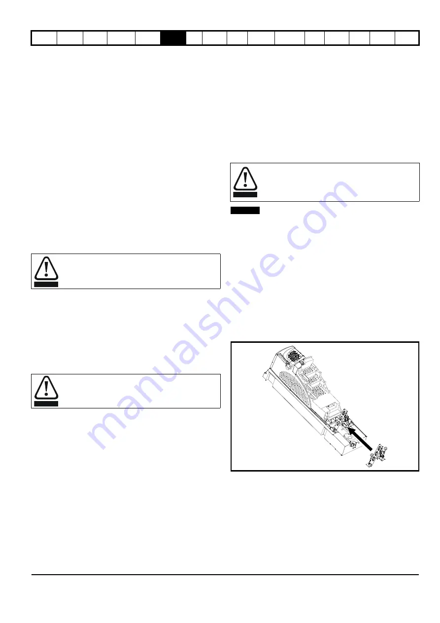
See Figure 6-18 for details on installing the grounding bracket.
Figure 6-18 Installation of grounding bracket (master/slave)
Loosen the ground connection nuts and slide the grounding bracket in
the direction shown. Once in place, re-tighten the ground connection
nuts.
A faston tab is located on the grounding bracket for the purpose of
connecting the drive 0V to ground should the user require to do so.
When the internal filter is installed the leakage current is
high. In this case a permanent fixed ground connection must
be provided, or other suitable measures taken to prevent a
safety hazard occurring if the connection is lost.
Only type B ELCB / RCD are suitable for use with 3 phase
inverter drives.
WARNING
WARNING
High ground leakage current
When an EMC filter is used, a permanent fixed ground
connection must be provided which does not pass through a
connector or flexible power cord. This includes the internal
EMC filter.
WARNING
NOTE


