


Safety
Information
Introduction
Product
Information
System
configuration
Mechanical
Installation
Electrical
Installation
Getting
Started
Basic
parameters
Running
the motor
Optimization
SMARTCARD
operation
Onboard
PLC
Advanced
parameters
Technical
Data
Diagnostics
UL Listing
Information
Unidrive SPM User Guide
261
Issue Number: 3 www.controltechniques.com
If Pr
6.09
is set to enable the catch a spinning motor function in open-
loop mode or closed-loop vector mode without position feedback,
(Pr
3.24
= 1 or 3) this parameter defines a scaling function used by the
algorithm that detects the speed of the motor. It is likely that for smaller
motors the default value of 1.0 is suitable, but for larger motors this
parameter may need to be increased. If the value of this parameter is too
large the motor may accelerate from standstill when the drive is enabled.
If the value of this parameter is too small the drive will detect the motor
speed as zero even if the motor is spinning.
13.21.9 Position modes
This parameter is used to set the position controller mode as shown in
the table below.
Rigid position control
In rigid position control the position error is always accumulated. This
means that, if for example, the slave shaft is slowed down due to
excessive load, the target position will eventually be recovered by
running at a higher speed when the load is removed.
Non-rigid position control
In non-rigid position control the position loop is only active when the 'At
Speed' condition is met (see Pr
3.06
). This allows slippage to occur while
the speed error is high.
Velocity feed forward
The position controller can generate a velocity feed forwards value from
the speed of the reference encoder. The feed-forwards value is passed
to menu, and so ramps may be included if required. Because the
position controller only has a proportional gain, it is necessary to use
velocity feed-forwards to prevent a constant position error that would be
proportional to the speed of the reference position.
If for any reason the user wishes to provide the velocity feed forward
from a source other than the reference position, the feed forward system
can be made inactive, i.e. Pr
13.10
= 2 or 4. The external feed forward
can be provided via Menu 1 from any of the frequency/speed references.
However, if the feed forward level is not correct a constant position error
will exist.
Relative jogging
If relative jogging is enabled the feedback position can be made to move
relative the reference position at the speed defined by Pr
13.17
.
Orientation
If Pr
13.10
is 5 the drive orientates the motor following a stop command.
If hold zero speed is enabled (Pr
6.08
= 1) the drive remains in position
control when orientation is complete and hold the orientation position. If
hold zero speed is not enabled the drive is disabled when orientation is
complete.
If Pr
13.10
is 6 the drive orientates the motor following a stop command
and whenever the drive is enabled provided that hold zero speed is
enabled (Pr
6.08
= 1). This ensures that the spindle is always in the
same position following the drive being enabled.
When orientating from a stop command the drive goes through the
following sequence:
1. The motor is decelerated or accelerated to the speed limit
programmed in Pr
13.12
, using ramps if these are enabled, in the
direction the motor was previously running.
2. When the ramp output reaches the speed set in Pr
13.12
, ramps are
disabled and the motor continues to rotate until the position is found
to be close to the target position (i.e. within 1/32 of a revolution). At
this point the speed demand is set to 0 and the position loop is
closed.
3. When the position is within the window defined by Pr
13.14
, the
orientation complete indication is given in Pr
13.15
.
The stop mode selected by Pr
6.01
has no effect if orientation is
enabled.
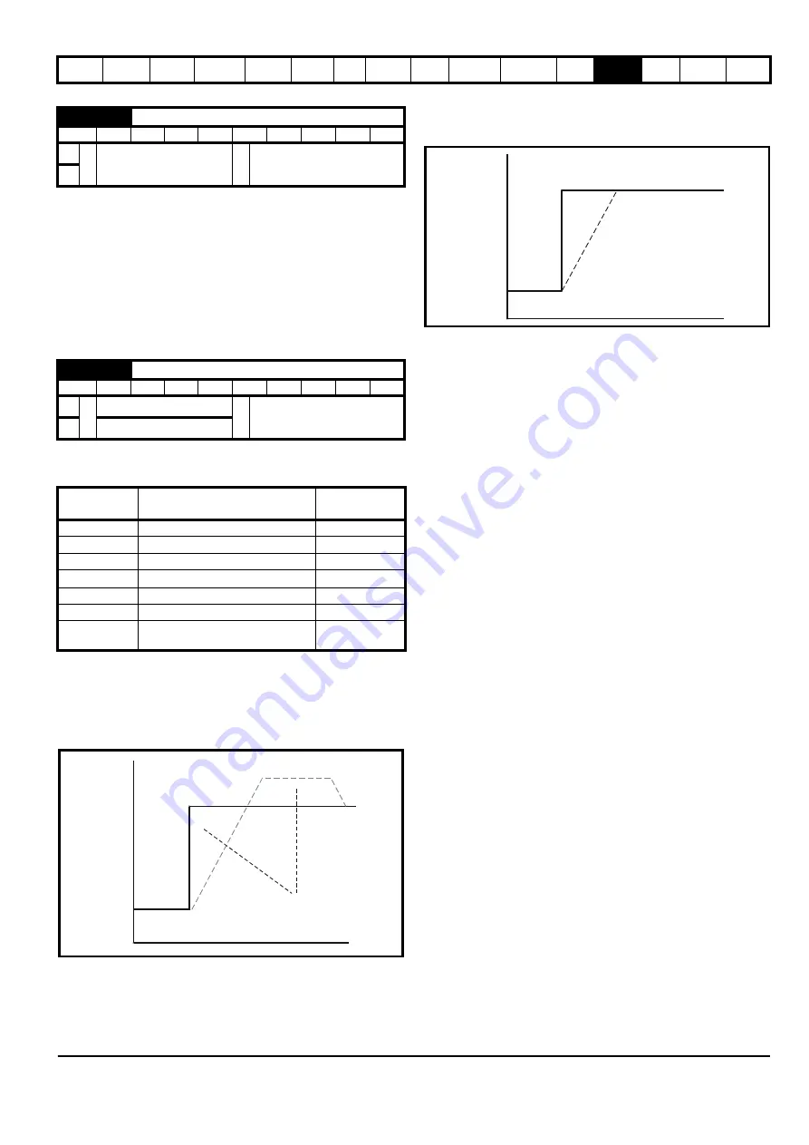
5.40
Spin start boost
RW
Uni
US
OL
Ú
0.0 to 10.0
Ö
1.0
VT
13.10
Position controller mode
RW
Uni
US
OL
Ú
0 to 2
Ö
0
CL
0 to 6
Parameter
value
Mode
Feed forward
active
0
Position controller disabled
1
Rigid position control
9
2
Rigid position control
3
Non-rigid position control
9
4
Non-rigid position control
5
Orientation on stop
6
Orientation on stop and when
drive enabled
Reference
Actual
Speed
Equal Areas
t
Reference
Actual
Speed


