


Safety
Information
Introduction
Product
Information
System
configuration
Mechanical
Installation
Electrical
Installation
Getting
Started
Basic
parameters
Running
the motor
Optimization
SMARTCARD
operation
Onboard
PLC
Advanced
parameters
Technical
Data
Diagnostics
UL Listing
Information
Unidrive SPM User Guide
293
Issue Number: 3 www.controltechniques.com
15.4 Displaying the trip history
The drive retains a log of the last 10 trips that have occurred in Pr
10.20
to Pr
10.29
and the corresponding multi-module drive module number
(Pr
6.49
= 0) or the trip time (Pr
6.49
= 1) for each trip in Pr
10.41
to
Pr
10.51
. The time of the trip is recorded from the powered-up clock (if
Pr
6.28
= 0) or from the run time clock (if Pr
6.28
= 1).
Pr
10.20
is the most recent trip, or the current trip if the drive is in a trip
condition (with the module number or trip time stored in Pr
10.41
and
Pr
10.42
). Pr
10.29
is the oldest trip (with the module number or trip time
stored in Pr
10.51
). Each time a new trip occurs, all the parameters
move down one, such that the current trip (and time) is stored in
Pr
10.20
(and Pr
10.41
to Pr
10.42
) and the oldest trip (and time) is lost
out of the bottom of the log.
If any parameter between Pr
10.20
and Pr
10.29
inclusive is read by
serial communications, then the trip number in Table 15-1
Trip
indications
on page 276 is the value transmitted.
15.5 Behaviour of the drive when tripped
If the drive trips, the output of the drive is disabled so that the drive stops
controlling the motor. If any trip occurs (except the UV trip) the following
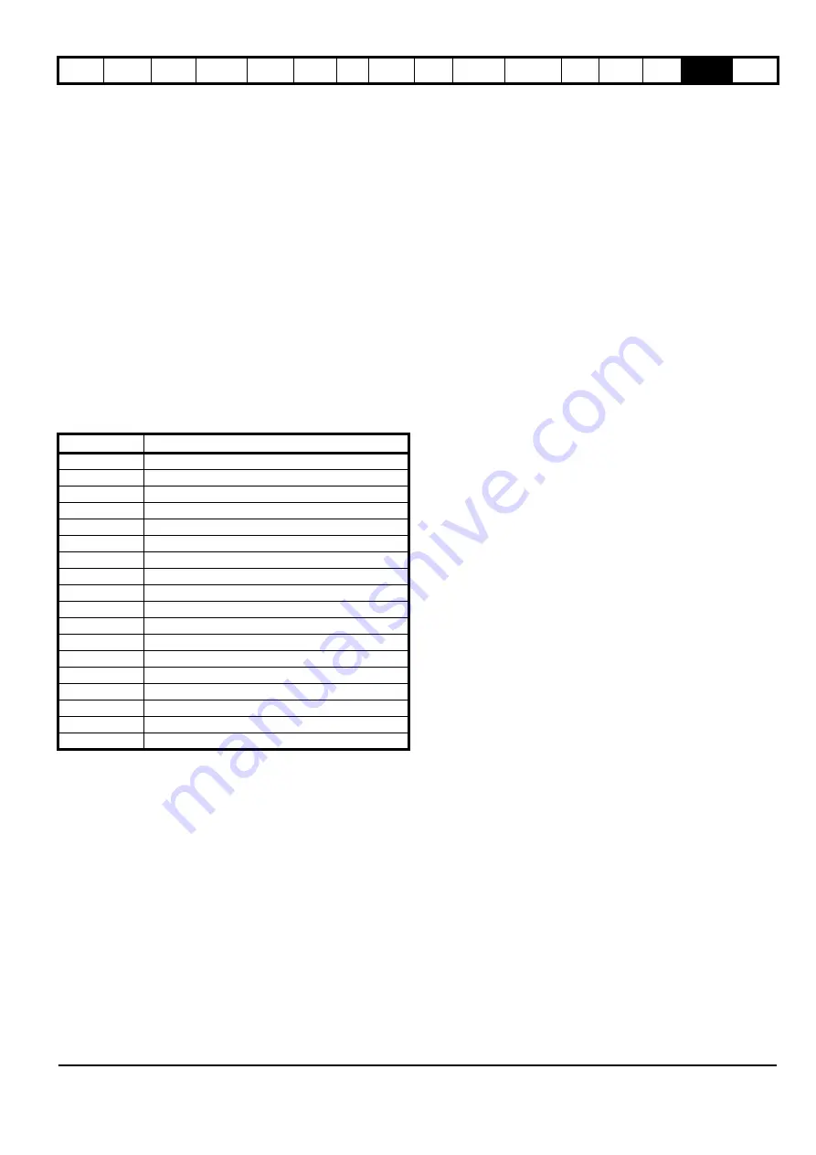
read only parameters are frozen until the trip is cleared. This is to help in
diagnosing the cause of the trip.
Analog and digital I/O
The analog and digital I/O on the drive continue to work correctly if a trip
occurs, except the digital outputs will go low if one of the following trips
occur: O.Ld1, PS.24V.
Drive logic functions
The drive logic functions (i.e. PID, variable selectors, threshold
detectors, etc.) continue to operate when the drive is tripped.
Onboard PLC program
The Onboard PLC program continues to run if the drive is tripped, except
if one of Onboard PLC program trips occur.
Braking IGBT
The braking IGBT continues to operate even when the output of the
drive is not enabled (except if the low voltage DC supply is being used),
but is only disabled if any of the following trips occurs or would occur if
another trip had not already become active: OI.Br, PS, It.Br or OV.
Parameter Description
1.01
Frequency/speed reference
1.02
Pre-skip filter reference
1.03
Pre-ramp reference
2.01
Post-ramp reference
3.01
Frequency slaving demand/Final speed ref
3.02
Speed feedback
3.03
Speed error
3.04
Speed controller output
4.01
Current magnitude
4.02
Active current
4.17
Reactive current
5.01
Output frequency
5.02
Output voltage
5.03
Power
5.05
DC bus voltage
7.01
Analog input 1
7.02
Analog input 2
7.03
Analog input 3


