


Safety
Information
Introduction
Product
Information
System
configuration
Mechanical
Installation
Electrical
Installation
Getting
Started
Basic
parameters
Running
the motor
Optimization
SMARTCARD
operation
Onboard
PLC
Advanced
parameters
Technical
Data
Diagnostics
UL Listing
Information
Unidrive SPM User Guide
117
Issue Number: 3 www.controltechniques.com
Pr
0.15
sets the ramp mode of the drive as shown below:
0: Fast ramp
Fast ramp is used where the deceleration follows the programmed
deceleration rate subject to current limits. This mode must be used if a
braking resistor is connected to the drive.
1: Standard ramp
Standard ramp is used. During deceleration, if the voltage rises to the
standard ramp level (Pr
2.08
) it causes a controller to operate, the output
of which changes the demanded load current in the motor. As the
controller regulates the link voltage, the motor deceleration increases as
the speed approaches zero speed. When the motor deceleration rate
reaches the programmed deceleration rate the controller ceases to
operate and the drive continues to decelerate at the programmed rate. If
the standard ramp voltage (Pr
2.08
) is set lower than the nominal DC bus
level the drive will not decelerate the motor, but it will coast to rest. The
output of the ramp controller (when active) is a current demand that is fed
to the frequency changing current controller (Open-loop modes) or the
torque producing current controller (Closed-loop vector or Servo modes).
The gain of these controllers can be modified with Pr
4.13
and Pr
4.14
.
2: Standard ramp with motor voltage boost
This mode is the same as normal standard ramp mode except that the
motor voltage is boosted by 20%. This increases the losses in the motor,
dissipating some of the mechanical energy as heat giving faster
deceleration.
Open-loop
When Pr
0.16
is set to 0, digital inputs T28 and T29 are set up
automatically with destinations according to the setting of the reference
select Pr
0.05
.
Setting Pr
0.16
to 1 disables this automatic set-up, allowing the user to
define the function of digital inputs T28 and T29.
Setting Pr
0.16
to 0 allows the user to disable the ramps. This is
generally used when the drive is required to closely follow a speed
reference which already contains acceleration and deceleration ramps.
Open-loop
Pr
0.17
sets the destination of digital input T29. This parameter is
normally set-up automatically according to the reference selected by
Pr
0.05
. In order to manually set-up this parameter, the T28 and T29
auto-selection disable (Pr
0.16
) must be set.
Closed-loop
A first order filter, with a time constant defined by Pr
0.17
, is provided on
the current demand to reduce acoustic noise and vibration produced as
a result of position feedback quantisation noise. The filter introduces a
lag in the speed loop, and so the speed loop gains may need to be
reduced to maintain stability as the filter time constant is increased.
Pr
0.18
sets the logic polarity for digital inputs and digital outputs. This
does not affect the drive enable input or the relay output.
In modes 2 & 3 a current loop loss trip is generated if the current falls
below 3mA.
In modes 2 & 4 the analog input level goes to 0.0% if the input current
falls below 4mA.
0.15 {2.04}
Ramp mode select
RW
Txt
US
OL
Ú
FASt (0)
Std (1)
Std.hV (2)
Ö
Std (1)
CL
Ú
FASt (0)
Std (1)
Ö
0.16 {8.39}
T28 and T29 auto-selection disable
RW
Bit
US
OL
Ú
OFF (0) or On (1)
Ö
OFF (0)
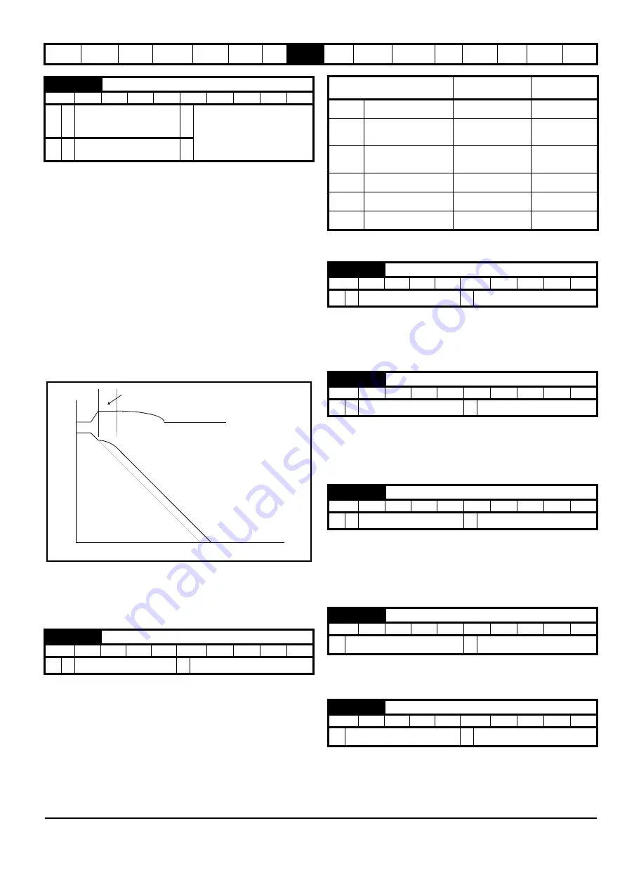
DC Bus voltage
Motor Speed
Programmed
deceleration
rate
t
Controller
operational
Reference select 0.05
Terminal 28
function
Terminal 29
function
A1.A2 (0)
Reference selection by
terminal input
Local / remote selector Jog select
A1.Pr (1)
Analogue reference 1 or
presets selected by
terminal input
Preset select bit 0
Preset select bit 1
A2.Pr (2)
Analogue reference 2 or
presets selected by
terminal input
Preset select bit 0
Preset select bit 1
Pr (3)
Preset reference selected
by terminal input
Preset select bit 0
Preset select bit 1
PAd (4)
Keypad reference
selected
Local / remote selector Jog select
Prc (5)
Precision reference
selected
Local / remote selector Jog select
0.16 {2.02}
Ramp enable
RW
Bit
US
CL
Ú
OFF (0) or On (1)
Ö
On (1)
0.17 {8.26}
T29 digital input destination
RW
Uni
DE
PT
US
OL
Ú
Pr
0.00
to Pr
21.51
Ö
Pr
6.31
0.17 {4.12}
Current demand filter time constant
RW
Uni
US
CL
Ú
0.0 to 25.0 ms
Ö
0.0
0.18 {8.29}
Positive logic select
RW
Bit
PT
US
Ú
OFF (0) or On (1)
Ö
On (1)
0.19 {7.11}
Analog input 2 mode
RW
Txt
US
Ú
0 to 6
Ö
VOLt (6)


