RSTi-OM User Manual
Section 3
GFK-3212A
Jun 2021
Configuring
14
1.
Securely attach the power cable between the male power connector (PWR In) and the power
supply.
2.
Either attach a power cable between the female power connector and another device to which
you want to provide power or securely attach a connector cap to prevent dust or liquids from
getting into the connector. Contact your Customer Sales Representative if you need to order
connector caps for the IOLM.
3.
Apply the power and verify that the following LEDs are lit indicating that you are ready to
attach your IO-Link or digital I/O devices.
a.
The V
S
LED lights.
b.
The ETH1/ETH2 LED lights on the connected port.
c.
The MOD and NET LEDs are lit.
d.
The IO-Link LEDs
flash (if no IO-Link device attached) or are lit if an IO-Link device is
attached.
Note: It takes approximately 25 seconds after power-up for the IO-Link Master to be ready for
operation.
If a PLC is connected, the NET LED is lit and green.
If the LEDs indicate that you are ready to go to the next installation step:
•
Program the IP address using a web interface. Refer to 3.4,
•
If using the rotary switches to set the IP address, then you are ready to attach devices using
2.1.4
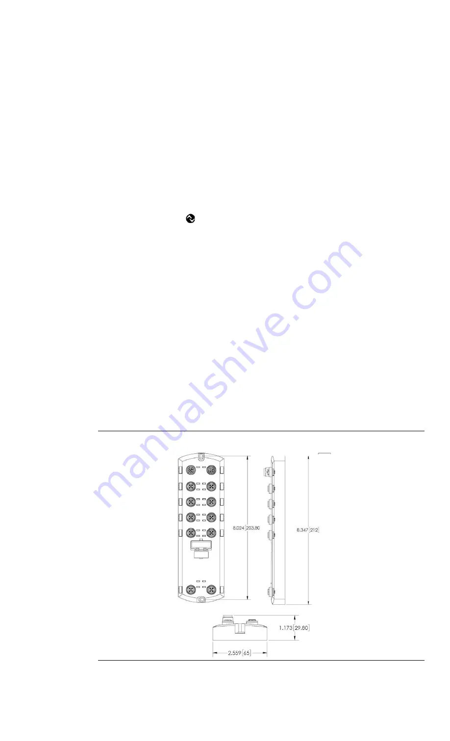
Mounting the IOLM
Use the following procedure to mount the IOLM. You can mount the IOLM on a mounting panel or a
machine.
1.
Verify that the mounting surface is level (flat) to prevent mechanical stress to the IOLM.
2.
Attach the IOLM to the surface with two 6 mm screws and washers, torque down to 8 Nm.
Figure 6: Mounting the IOLM 8 PNIO L


