Standard Circuits
Software Overview
•
11
-
7
Any user-defined Pump Down and Run-Off times will
be observed as normal.
Electric Defrost
Electric defrost uses electric heaters to defrost the
evaporator coil. During electric defrost, the application
will turn the Defrost output ON to activate the heaters con-
nected to the output.
Any user-defined Pump Down and Run-Off times will
be observed as normal.
11.3.2.3 Defrost Termination
Both the start and the end times of a defrost cycle are
determined by the user. The Pump Down, Defrost, and
Run-Off stages all have fixed durations, and when the last
stage of the cycle is complete, defrost is terminated.
However, a Standard Circuit application may be pro-
grammed to terminate the Defrost stage of the defrost
cycle early if the temperature inside the case rises above a
fail-safe temperature setpoint (called the termination set-
point). For certain defrost types, defrost heat may also be
“pulsed” in order to keep the temperature below the set-
point without terminating defrost.
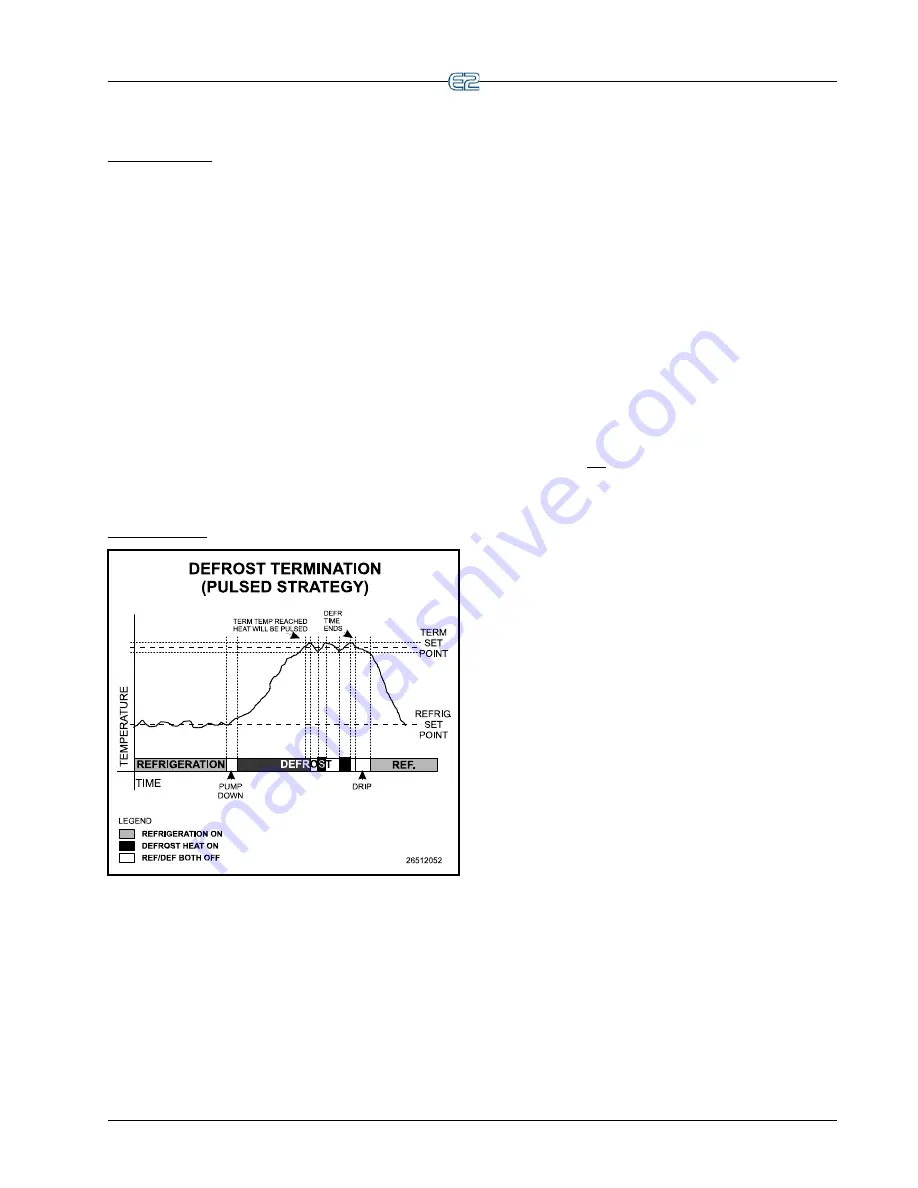
Pulsed Defrost
Figure 11-4
- Defrost Termination (Pulsed)
Pulsed Defrost is only available if the circuit is using
heated defrost, such as Electric or Hot Gas defrost.
Pulsed Defrost is similar to the Temperature Termina-
tion strategy outlined in
Section 11.3.2.3
, except a defrost
cycle
always
continues for the full programmed duration.
When the termination temperature rises above the set-
point, defrost does not end. Instead, the defrost heat is
turned OFF until the case temperature falls below the set-
point, at which time the output will come back ON to con-
tinue heating.
Figure 11-4
illustrates what happens in a pulsed
defrost cycle. In this example, the case reaches its termina-
tion temperature approximately 2/3 of the way into its
defrost cycle. Defrost continues, but defrost heat is turned
OFF until the temperature falls below the setpoint, at
which point the heat is turned back ON.
Defrost heat will continue to be pulsed in this manner
until the defrost time has passed. The defrost cycle will
then begin the Run-Off period, and then restart refrigera-
tion.
11.3.2.4 Emergency Defrost
When necessary, a user can initiate an emergency
defrost cycle in a circuit. Emergency defrost cycles are
similar to normal defrost cycles, except an emergency
defrost cycle will ignore all calls for termination and
remain in defrost for the entire programmed defrost time.
For cases using a pulsed defrost strategy, this means the
defrost heat will not be pulsed during emergency defrost.
Emergency defrosts are initiated by the user from the
Standard Circuit Bypass screen (see
Section 12.6, Manual
Defrost and Clean Mode
).
11.3.2.5 Hot Gas Defrost with ESR8 and
MultiFlex ESR
If an ESR8 or MultiFlex ESR is used on a circuit that
uses hot gas defrost, values for circuits in defrost are
forced OPEN (100%) to allow hot gas to flow through the
evaporators.
11.3.3 Clean and Door Switches
11.3.3.1 Clean Switches
A Standard Circuit application may be configured to
entirely shut down a case circuit so that it may be cleaned
or serviced. A case circuit enters clean mode when it
receives a signal from an input called the clean switch.
Clean switches may be set up as either “Switched” or
“Timed.” If a clean switch is configured as “switched,” the
circuit enters clean mode when the switch is turned ON,
and it remains in clean mode until the switch is turned
OFF. If a clean switch is configured as “timed,” the circuit
enters clean mode when the switch is turned ON, and it
remains in clean mode for a fixed user-defined amount of
time.
During clean mode, the Fan, Defrost, and Refrigera-
tion Solenoid outputs are all turned OFF, and the liquid
line solenoid is CLOSED.
If desired, a notice may be sent to the E2’s Alarm Log
so that the E2 can keep track of clean modes and times.
Summary of Contents for E2
Page 2: ......
Page 4: ......
Page 16: ......
Page 24: ......
Page 48: ......
Page 55: ......
Page 56: ......
Page 72: ...6 16 E2 RX BX CX I O Manual 026 1614 Rev 4 5 JAN 2013 ...
Page 75: ...BACnet The RS485 Network and Hardware Setup 6 19 ...
Page 79: ...BACnet The RS485 Network and Hardware Setup 6 23 ...
Page 80: ...6 24 E2 RX BX CX I O Manual 026 1614 Rev 4 5 JAN 2013 ...
Page 81: ......
Page 82: ......
Page 92: ...8 6 E2 RX BX CX I O Manual 026 1614 Rev 4 5 JAN 2013 ...
Page 94: ...8 8 E2 RX BX CX I O Manual 026 1614 Rev 4 5 JAN 2013 ...
Page 114: ......
Page 144: ......
Page 203: ......
Page 204: ......
Page 226: ......
Page 253: ......
Page 254: ......
Page 257: ......
Page 258: ......
Page 267: ......
Page 268: ......
Page 270: ......
Page 282: ......


