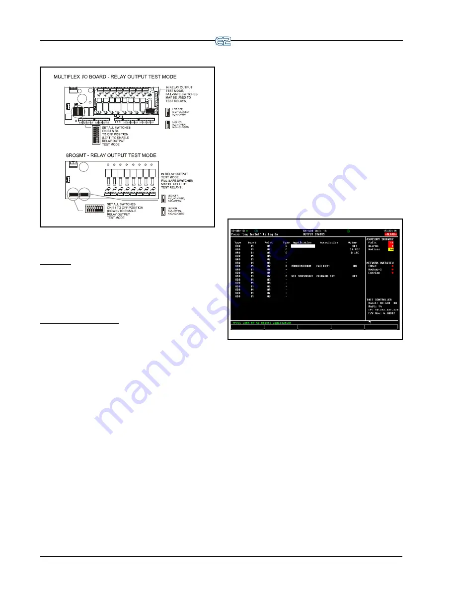
Figure 9-9
- Relay Output Test Mode for MF I/O Board
9-12
•
E2 RX/BX/CX I&O Manual
026-1614 Rev 4 5-JAN-2013
9.2.5
Wiring Outputs to Points
Old 8ROs
The old design of 8RO (P/N 810-3002) used points
with two terminals on them. To connect output devices to
these points, wire the point terminals in series with the
load, so that the path is closed when the 8RO relay is
CLOSED and open when the 8RO relay is OPEN.
New 8ROs and 8RO-FCs
All other E2-compatible output boards, including the
new design of 8RO
(P/N 810-3005)
, the 8RO-FC, and
have Form C contacts.
Figure 9-8
shows how to wire the
three-terminal Form C contact.
One wire of the two-wire 8RO-FC connection should
always be connected to the middle terminal. The second
wire must either be connected to the N.C. terminal (if you
want the path to be closed when the relay is de-energized)
or the N.O. terminal (if you want the path to be open
during power failure.
9.2.6
The Output LED
Each output point on an output board has an indicator
LED that shows the status of the output. This LED is lit to
show the output is ON, and unlit to show the output is
OFF.
The definition of ON and OFF in this case is deter-
mined by the position of the fail-safe dip switch (see
Table
9-3
). Therefore, if the output’s switch is UP, an illuminated
LED means the path is CLOSED, but if the switch is
DOWN, an illuminated LED means the path is OPEN.
9.2.7
Output Setup in E2
In order for the E2 to properly control devices that are
hooked to an I/O board, you must first tell the E2 what
type of output the devices require. This is achieved from
the Output Definitions/Status screen.
9.2.7.1
Configuring a Point from the
Output Definitions/Status Screen
To configure a point, go to the Output Definitions/Sta-
tus screen by pressing Alt + O or:
1.
Press
to open the Main Menu
2.
Press
(System Configuration)
3.
Press
(Output Definitions)
The Output Status screen opens:
Figure 9-10
- Output Status Screen
To configure a point, use the up and down arrow keys
to move the cursor to the point you wish to set up, and
press
(SETUP).
If you press
to set up a 4AO output point, the E2
will automatically transfer you to the Analog Output
screen
Figure 9-6
. For all other output board types, press-
ing
will bring up a pop-up menu such as the one
shown in
Figure 9-11
. This menu will prompt you to spec-
ify the output as either Digital, Pulse, or One Shot. Press
if the output is Digital, press
if the output is Pulse,
press
if the output is One Shot, or press
to cancel
setup.
Summary of Contents for E2
Page 2: ......
Page 4: ......
Page 16: ......
Page 24: ......
Page 48: ......
Page 55: ......
Page 56: ......
Page 72: ...6 16 E2 RX BX CX I O Manual 026 1614 Rev 4 5 JAN 2013 ...
Page 75: ...BACnet The RS485 Network and Hardware Setup 6 19 ...
Page 79: ...BACnet The RS485 Network and Hardware Setup 6 23 ...
Page 80: ...6 24 E2 RX BX CX I O Manual 026 1614 Rev 4 5 JAN 2013 ...
Page 81: ......
Page 82: ......
Page 92: ...8 6 E2 RX BX CX I O Manual 026 1614 Rev 4 5 JAN 2013 ...
Page 94: ...8 8 E2 RX BX CX I O Manual 026 1614 Rev 4 5 JAN 2013 ...
Page 114: ......
Page 144: ......
Page 203: ......
Page 204: ......
Page 226: ......
Page 253: ......
Page 254: ......
Page 257: ......
Page 258: ......
Page 267: ......
Page 268: ......
Page 270: ......
Page 282: ......


