


Be sure headlamp, tail
lamp,
stop lamp and turn
signals are operating properly before riding. Poor
visibility of rider to other motorists can result in
death or serious injury.
9. Check for any fuel, oil, coolant or hydraulic fluid
leaks.
10. Check chain for wear and damage. Service as neces-
sary.
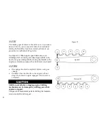
SIDESTAND INTERLOCK
Some models are equipped with a sidestand interlock
feature. If the sidestand is down, the transmission is in
gear, and the clutch is released, the vehicle will stall.
The message SIDE STAND will be displayed in the in-
strument cluster to indicate the condition.
The vehicle will start and run with the sidestand down
while the transmission is in neutral and the clutch is re-
leased.
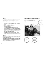
STARTING THE ENGINE
Shift transmission to neutral before starting engine
to prevent accidental movement, which could result
in death or serious injury.
The engine should be allowed to run slowly for 30-60
seconds. This will allow the engine to warm up and
let oil reach all surfaces needing lubrication. Failure
to comply can result in engine damage.
NOTE
EBR motorcycles feature a starter interlock. Before
starting the engine, all the following conditions must be
met.
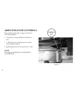
1. Engine OFF/RUN switch on handlebar control
group must be in the ON position.
2.
Clutch lever must be applied (pulled in) before start-
ing motorcycle in gear. It is not necessary to apply
clutch lever if motorcycle is being started in neutral.
78
Summary of Contents for EBR 1190RS 2013
Page 1: ...2013 EBR OWNERS MANUAL EBR 1190RS MODEL Part Number C1000 2B6 1 ...
Page 3: ...3 ...
Page 23: ...TABLE OF CONTENTS Notes 23 ...
Page 24: ...TABLE OF CONTENTS Notes 24 ...
Page 36: ...VEHICLE IDENTIFICATION NUMBER EBR 1190RS MODELS 36 ...
Page 39: ...NOTES 39 ...
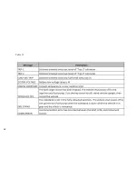
Page 42: ...Table 5 Drivetrain Table 6 Cooling System Table 7 Liquid Capacities Table 8 Sprocket teeth 42 ...
Page 43: ...Table 9 Transmission Gear Ratios Table 11 Tires Table 10 Bulb Chart 43 ...
Page 44: ...Table 12 Dimensions Table 13 Weights 44 ...
Page 64: ...Table 15 64 ...
Page 66: ...Figure 24 Upshift Pattern Figure 25 Downshift Pattern 66 ...
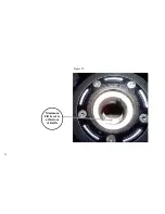
Page 71: ...Maximum Fill Level is at Bottom of Baffle Figure 29 71 ...
Page 84: ...Figure 34 Seat Fasteners Seat removal 4 T 30 screws 84 ...
Page 92: ...92 Notes ...
Page 93: ...93 Notes ...
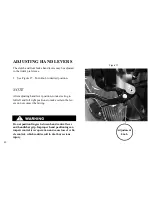
Page 116: ...Figure 52 Adjustment Measurement 35 mm Adjustment Distance 116 ...
Page 117: ...117 Notes ...
Page 176: ...176 ...
Page 177: ...177 ...
Page 178: ...178 ...


