


Front Fork Rebound Damping...............................
97
Fuel.........................................................................
47
Fuel Filter: ……......................................................
112
Fuel Filler Cap: …………......................................
70
I
Idle Speed.............................................................
13
4
Indicator Lamps....................................................
57
Ignition Key Switch: ……………………...........
48
Ignition Timing: …………..................................
13
4
Information line....................................................
59
Initialization Sequence.........................................
62
Inspection
: Tires
.................................................... 13
3
J
Jump-Starting ……………....................................
1
40
L
Labels: ……………..............................................
40
Lap timer…………………………………………
63
LCD Screen...........................................................
54
Locking Steering...................................................
50
Low Battery Voltage Lamp...................................
62
Low Fuel Lamp.....................................................
60
Low Fuel Odometer (F-trip)..................................
60
171
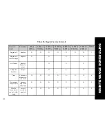
Initial Service Check: First 620 Miles................
104
Summary of Contents for EBR 1190RS 2013
Page 1: ...2013 EBR OWNERS MANUAL EBR 1190RS MODEL Part Number C1000 2B6 1 ...
Page 3: ...3 ...
Page 23: ...TABLE OF CONTENTS Notes 23 ...
Page 24: ...TABLE OF CONTENTS Notes 24 ...
Page 36: ...VEHICLE IDENTIFICATION NUMBER EBR 1190RS MODELS 36 ...
Page 39: ...NOTES 39 ...
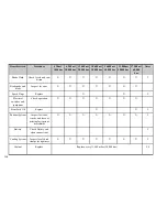
Page 42: ...Table 5 Drivetrain Table 6 Cooling System Table 7 Liquid Capacities Table 8 Sprocket teeth 42 ...
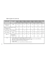
Page 43: ...Table 9 Transmission Gear Ratios Table 11 Tires Table 10 Bulb Chart 43 ...
Page 44: ...Table 12 Dimensions Table 13 Weights 44 ...
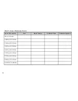
Page 64: ...Table 15 64 ...
Page 66: ...Figure 24 Upshift Pattern Figure 25 Downshift Pattern 66 ...
Page 71: ...Maximum Fill Level is at Bottom of Baffle Figure 29 71 ...
Page 84: ...Figure 34 Seat Fasteners Seat removal 4 T 30 screws 84 ...
Page 92: ...92 Notes ...
Page 93: ...93 Notes ...
Page 116: ...Figure 52 Adjustment Measurement 35 mm Adjustment Distance 116 ...
Page 117: ...117 Notes ...
Page 176: ...176 ...
Page 177: ...177 ...
Page 178: ...178 ...


