


CALIFORNIA EVAPORATIVE
EMISSION CONTROL
All new 2012 EBR motorcycles sold in the state of Califor-
nia are equipped with an evaporative emission control sys-
tem.
This system is designed to meet the CARB regulations in
effect at the time of manufacture.
The system requires a small amount of maintenance. Peri-
odic inspection is required to make sure hoses are properly
routed, not kinked or blocked, and that all fittings are se-
cure. Mounting hardware should also be checked periodi-
cally for tightness.
EPA NOISE REGULATIONS IN
THE UNITED STATES
EPA Noise regulations require that the following state-
ments be included in the Owner‟s Manual.
TAMPERING WITH NOISE CONTROL SYSTEM
PROHIBITED: Federal law prohibits the following
acts of the causing thereof. (1.) The removal or ren-
dering inoperative by any person other than for the
purposes of maintenance, repair, or replacement of
any device or element of design incorporated into any
new vehicle for the purpose of noise control prior to
its sale or delivery to the ultimate purchaser or while
it is in use, or (2) the use of the vehicle after such
device or element of design has been removed or ren-
dered inoperative by any person.
AMONG THOSE ACTS PRESUMED TO CONSTI-
TUTE TAMPERING ARE THE ACTS LISTED BE-
LOW.
1. Replacing the muffler(s) and/or entire exhaust
system with parts not certified to be noise legal
for street use.
2. Removing or modifying the muffler internal baf-
fles in any way.
3. Replacing the air intake/cleaner assembly with
one not certified to be noise legal for street use.
4. Modifying the air intake/cleaner assembly in
such a way as to make the vehicle no longer
noise legal for street use.
152
Summary of Contents for EBR 1190RS 2013
Page 1: ...2013 EBR OWNERS MANUAL EBR 1190RS MODEL Part Number C1000 2B6 1 ...
Page 3: ...3 ...
Page 23: ...TABLE OF CONTENTS Notes 23 ...
Page 24: ...TABLE OF CONTENTS Notes 24 ...
Page 36: ...VEHICLE IDENTIFICATION NUMBER EBR 1190RS MODELS 36 ...
Page 39: ...NOTES 39 ...
Page 42: ...Table 5 Drivetrain Table 6 Cooling System Table 7 Liquid Capacities Table 8 Sprocket teeth 42 ...
Page 43: ...Table 9 Transmission Gear Ratios Table 11 Tires Table 10 Bulb Chart 43 ...
Page 44: ...Table 12 Dimensions Table 13 Weights 44 ...
Page 64: ...Table 15 64 ...
Page 66: ...Figure 24 Upshift Pattern Figure 25 Downshift Pattern 66 ...
Page 71: ...Maximum Fill Level is at Bottom of Baffle Figure 29 71 ...
Page 84: ...Figure 34 Seat Fasteners Seat removal 4 T 30 screws 84 ...
Page 92: ...92 Notes ...
Page 93: ...93 Notes ...
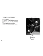
Page 116: ...Figure 52 Adjustment Measurement 35 mm Adjustment Distance 116 ...
Page 117: ...117 Notes ...
Page 176: ...176 ...
Page 177: ...177 ...
Page 178: ...178 ...


