HYDRAULIC CLUTCH
General
The clutch is hydraulically actuated. Squeezing the left
hand lever actuates the clutch master cylinder applying
hydraulic pressure through the clutch fluid line to the
secondary clutch actuator. The secondary actuator acts
on the clutch pressure plate compressing the clutch
springs and disengaging the clutch.
The slipper action clutch reduces undesired engine
braking when the engine is down shifted at speed.
Checking Fluid Level
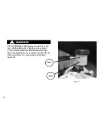
Refer to table 26. Check the fluid level as follows:
1. Stand the motorcycle upright (not leaning on the
sidestand) on a level surface, turn the handlebar so
the clutch master cylinder reservoir is level.
2. Verify the fluid level in the fluid reservoir.
3. If the fluid level is at or below the MIN line, rotate
the front forks to access the fluid reservoir and re-
move the cover, stiffener and diaphragm.
4. Inspect the cover, stiffener and diaphragm for dam-
age. Replace the diaphragm if necessary.
D.O.T. 4 hydraulic brake fluid is used in the hydrau-
lic clutch. Use AmsOil Series 600 racing DOT4 rac-
ing Brake Fluid or equivalent. Do not use other types
of fluids as they are not compatible and could cause
equipment damage.
Do not allow dirt or debris to enter the master cylin-
der reservoir. Dirt or debris in the reservoir can
cause improper operation and equipment damage.
128
Summary of Contents for EBR 1190RS 2013
Page 1: ...2013 EBR OWNERS MANUAL EBR 1190RS MODEL Part Number C1000 2B6 1 ...
Page 3: ...3 ...
Page 23: ...TABLE OF CONTENTS Notes 23 ...
Page 24: ...TABLE OF CONTENTS Notes 24 ...
Page 36: ...VEHICLE IDENTIFICATION NUMBER EBR 1190RS MODELS 36 ...
Page 39: ...NOTES 39 ...
Page 42: ...Table 5 Drivetrain Table 6 Cooling System Table 7 Liquid Capacities Table 8 Sprocket teeth 42 ...
Page 43: ...Table 9 Transmission Gear Ratios Table 11 Tires Table 10 Bulb Chart 43 ...
Page 44: ...Table 12 Dimensions Table 13 Weights 44 ...
Page 64: ...Table 15 64 ...
Page 66: ...Figure 24 Upshift Pattern Figure 25 Downshift Pattern 66 ...
Page 71: ...Maximum Fill Level is at Bottom of Baffle Figure 29 71 ...
Page 84: ...Figure 34 Seat Fasteners Seat removal 4 T 30 screws 84 ...
Page 92: ...92 Notes ...
Page 93: ...93 Notes ...
Page 116: ...Figure 52 Adjustment Measurement 35 mm Adjustment Distance 116 ...
Page 117: ...117 Notes ...
Page 176: ...176 ...
Page 177: ...177 ...
Page 178: ...178 ...

