


WARNING
!
Avoid spills. Slowly remove filler cap. Do not fill
above bottom of filler neck insert, leaving air space
for fuel expansion. Secure filler cap after refueling.
Gasoline is extremely flammable and highly explo-
sive, which could result in death or serious injury.
WARNING
!
Use care when refueling. Pressurized air in fuel tank
can force gasoline to escape through filler tube. Gas-
oline is extremely flammable and highly explosive,
which could result in death or serious injury.
CAUTION
!
WARNING
!
Do not remove radiator filler cap when engine is hot.
The cooling system is under pressure and hot coolant
and steam can escape, which could cause severe
burns. Allow engine to cool before servicing cooling
system.
Cooling fans operate automatically, even when the
ignition switch is off. Keep hands away from fan
blades. Contact with a rotating fan blade can result
in minor or moderate injury.
CAUTION
!
At operating temperature, the radiator and oil cooler
contain hot fluids. Contact with the radiator or oil
cooler can result in minor or moderate burns.
WARNING
!
Engine exhaust from this product contains chemicals
known to the State of California to cause cancer, and
birth defects or other reproductive harm.
WARNING
!
Wheel weights may contain lead and lead com-
pounds, chemicals known to the State of California
to cause cancer, birth defects, or other reproductive
harm.
26
Summary of Contents for EBR 1190RS 2013
Page 1: ...2013 EBR OWNERS MANUAL EBR 1190RS MODEL Part Number C1000 2B6 1 ...
Page 3: ...3 ...
Page 23: ...TABLE OF CONTENTS Notes 23 ...
Page 24: ...TABLE OF CONTENTS Notes 24 ...
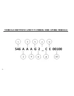
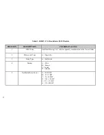
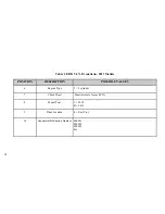
Page 36: ...VEHICLE IDENTIFICATION NUMBER EBR 1190RS MODELS 36 ...
Page 39: ...NOTES 39 ...
Page 42: ...Table 5 Drivetrain Table 6 Cooling System Table 7 Liquid Capacities Table 8 Sprocket teeth 42 ...
Page 43: ...Table 9 Transmission Gear Ratios Table 11 Tires Table 10 Bulb Chart 43 ...
Page 44: ...Table 12 Dimensions Table 13 Weights 44 ...
Page 64: ...Table 15 64 ...
Page 66: ...Figure 24 Upshift Pattern Figure 25 Downshift Pattern 66 ...
Page 71: ...Maximum Fill Level is at Bottom of Baffle Figure 29 71 ...
Page 84: ...Figure 34 Seat Fasteners Seat removal 4 T 30 screws 84 ...
Page 92: ...92 Notes ...
Page 93: ...93 Notes ...
Page 116: ...Figure 52 Adjustment Measurement 35 mm Adjustment Distance 116 ...
Page 117: ...117 Notes ...
Page 176: ...176 ...
Page 177: ...177 ...
Page 178: ...178 ...


