


These Brake tasks may include:
1. Inspecting front and rear brake pads and brake disks
for wear.
2. Checking the fluid level in the front and rear master
cylinder reservoirs.
3. Replacing the front and rear brake pads and pin.
4. Changing the brake fluid and having the brakes ser-
viced. Use only D.O.T. 4 Hydraulic Brake Fluid.
Use Amsoil Series 600 racing DOT4 racing Brake
Fluid or equivalent.
Always take your motorcycle to an EBR Dealer for
brake system maintenance.
Direct contact of D.O.T. 4 brake fluid with eyes can
cause irritation. Avoid eye contact. In case of eye
contact flush with large amounts of water and get
medical attention. Swallowing large amounts of
D.O.T. 4 brake fluid can cause digestive discomfort.
If swallowed, obtain medical attention. Use in a well
ventilated area. KEEP OUT OF REACH OF CHIL-
DREN.
D.O.T. 4 brake fluid will damage painted and body
panel surfaces it comes in contact with. Always use
caution and protect surfaces form spills whenever
brake work is performed. Failure to comply can re-
sult in cosmetic damage.
NOTE:
Use nickel based anti-seize on all bolts
that are being installed in front and rear wheels
131
Summary of Contents for EBR 1190RS 2013
Page 1: ...2013 EBR OWNERS MANUAL EBR 1190RS MODEL Part Number C1000 2B6 1 ...
Page 3: ...3 ...
Page 23: ...TABLE OF CONTENTS Notes 23 ...
Page 24: ...TABLE OF CONTENTS Notes 24 ...
Page 36: ...VEHICLE IDENTIFICATION NUMBER EBR 1190RS MODELS 36 ...
Page 39: ...NOTES 39 ...
Page 42: ...Table 5 Drivetrain Table 6 Cooling System Table 7 Liquid Capacities Table 8 Sprocket teeth 42 ...
Page 43: ...Table 9 Transmission Gear Ratios Table 11 Tires Table 10 Bulb Chart 43 ...
Page 44: ...Table 12 Dimensions Table 13 Weights 44 ...
Page 64: ...Table 15 64 ...
Page 66: ...Figure 24 Upshift Pattern Figure 25 Downshift Pattern 66 ...
Page 71: ...Maximum Fill Level is at Bottom of Baffle Figure 29 71 ...
Page 84: ...Figure 34 Seat Fasteners Seat removal 4 T 30 screws 84 ...
Page 92: ...92 Notes ...
Page 93: ...93 Notes ...
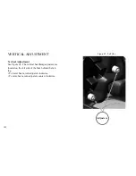
Page 116: ...Figure 52 Adjustment Measurement 35 mm Adjustment Distance 116 ...
Page 117: ...117 Notes ...
Page 176: ...176 ...
Page 177: ...177 ...
Page 178: ...178 ...


