


Do not exceed the motorcycles Gross Vehicle Weight
Rating (GVWR) or the Gross Axle Weight Rating
(GAWR). Exceeding these weight ratings can affect
stability and handling, which could result in death or
serious injury.
GVWR is the sum of the weight of the motorcycle,
accessories, and the maximum weight of the rider,
and cargo that can be safely carried.
GAWR is the maximum amount of weight that can
be safely carried on each axle.
The GVWR and GAWR are shown on the infor-
mation plate located on the frame steering head.
Do not pull a trailer with a motorcycle. Pulling a trailer
can cause tire overload, reduced braking efficiency and
adversely affect stability and handling, which could re-
sult in death or serious injury.
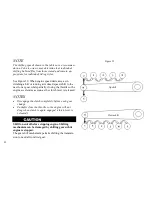
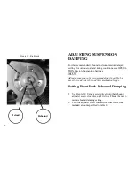
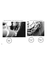
ADJUSTING PRELOAD
See OPERATION, Suspension Adjustments, for more in-
formation about suspension tuning.
Rear Shock Preload Settings
See Figure 38. The factory setting is 8 revolutions clock-
wise from the minimum position. The minimum position is
found by turning the adjustor counter clockwise until it
stops. Do not force. For recommended spring preload, see
OPERATION, Factory Suspension Settings.
96
Summary of Contents for EBR 1190RS 2013
Page 1: ...2013 EBR OWNERS MANUAL EBR 1190RS MODEL Part Number C1000 2B6 1 ...
Page 3: ...3 ...
Page 23: ...TABLE OF CONTENTS Notes 23 ...
Page 24: ...TABLE OF CONTENTS Notes 24 ...
Page 36: ...VEHICLE IDENTIFICATION NUMBER EBR 1190RS MODELS 36 ...
Page 39: ...NOTES 39 ...
Page 42: ...Table 5 Drivetrain Table 6 Cooling System Table 7 Liquid Capacities Table 8 Sprocket teeth 42 ...
Page 43: ...Table 9 Transmission Gear Ratios Table 11 Tires Table 10 Bulb Chart 43 ...
Page 44: ...Table 12 Dimensions Table 13 Weights 44 ...
Page 64: ...Table 15 64 ...
Page 66: ...Figure 24 Upshift Pattern Figure 25 Downshift Pattern 66 ...
Page 71: ...Maximum Fill Level is at Bottom of Baffle Figure 29 71 ...
Page 84: ...Figure 34 Seat Fasteners Seat removal 4 T 30 screws 84 ...
Page 92: ...92 Notes ...
Page 93: ...93 Notes ...
Page 116: ...Figure 52 Adjustment Measurement 35 mm Adjustment Distance 116 ...
Page 117: ...117 Notes ...
Page 176: ...176 ...
Page 177: ...177 ...
Page 178: ...178 ...


