


Pay strict attention to road surfaces and wind conditions.
Your motorcycle may be subject to the following upset-
ting forces:
1. Irregular pavement surfaces, such as holes, patches.
2. Wind blasts from passing vehicles.
3. Oil spills, gravel, etc. on road surface.
4. Inappropriate rider control input.
These forces may influence the handling characteristics
of your motorcycle. If this happens, reduce speed and
guide the motorcycle with a relaxed grip to a controlled
condition. Do not brake abruptly or force the handlebar;
this may aggravate an unstable condition.
NOTE
New riders should gain experience under various con-
ditions while riding at moderate speeds. Operate your
motorcycle defensively. Remember, a motorcycle does
not afford the same protection as an automobile in an
accident. One of the most common accident situations
occurs when the driver of the other vehicle fails to see
or recognize a motorcycle and turns left into the on-
coming motorcyclist. Riding with headlamp high beam
switch on during daylight hours will increase your
chances of visibility. Wear a helmet, clothing, and foot
gear suited for motorcycle riding. Bright or light colors
are best for greater visibility in traffic, especially at
night. Avoid loose, flowing garments and scarves.
28
Summary of Contents for EBR 1190RS 2013
Page 1: ...2013 EBR OWNERS MANUAL EBR 1190RS MODEL Part Number C1000 2B6 1 ...
Page 3: ...3 ...
Page 23: ...TABLE OF CONTENTS Notes 23 ...
Page 24: ...TABLE OF CONTENTS Notes 24 ...
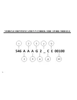
Page 36: ...VEHICLE IDENTIFICATION NUMBER EBR 1190RS MODELS 36 ...
Page 39: ...NOTES 39 ...
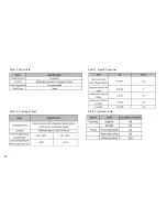
Page 42: ...Table 5 Drivetrain Table 6 Cooling System Table 7 Liquid Capacities Table 8 Sprocket teeth 42 ...
Page 43: ...Table 9 Transmission Gear Ratios Table 11 Tires Table 10 Bulb Chart 43 ...
Page 44: ...Table 12 Dimensions Table 13 Weights 44 ...
Page 64: ...Table 15 64 ...
Page 66: ...Figure 24 Upshift Pattern Figure 25 Downshift Pattern 66 ...
Page 71: ...Maximum Fill Level is at Bottom of Baffle Figure 29 71 ...
Page 84: ...Figure 34 Seat Fasteners Seat removal 4 T 30 screws 84 ...
Page 92: ...92 Notes ...
Page 93: ...93 Notes ...
Page 116: ...Figure 52 Adjustment Measurement 35 mm Adjustment Distance 116 ...
Page 117: ...117 Notes ...
Page 176: ...176 ...
Page 177: ...177 ...
Page 178: ...178 ...


