


NOTES
If you leave the key in the ON or PARKING LAMP
position for an extended length of time while
parked, the lamps will eventually discharge the bat-
tery.
Record your key number in the space provided at
the front of this Owner‟s Manual. The key number
is pressed on a plastic tab that comes with the keys.
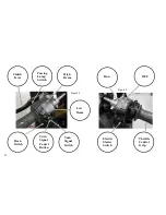
Turning Motorcycle On/Off
1. See Figure 3. Turn the key clockwise to the ON po-
sition.
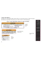
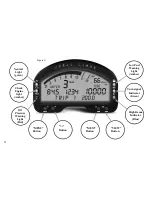
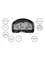
2. See Figure 7. Check the operation of the Instrument
Cluster.
A. The Instrument Cluster will sweep the ta-
chometer and calibrate at zero RPM.
B. The Instrument Cluster will perform a bulb
check. All indicator lamps and warning lamps will illu-
minate briefly. Check that all lamps are lit.
C. The LCD screen will illuminate and display
the time, odometer (in its last selected mode before key
off), digital speedometer, and an introductory text mes-
sage.
NOTES
-The check engine lamp may remain lit
for up to four seconds longer than other lamps. If
the check engine lamp remains on longer, refer to
CONTROLS AND INDICATORS, Warning
Lamps for more information.
3. See Figure 3. Turn the key counterclockwise to
the OFF position to shut the motorcycle off.
49
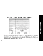
Summary of Contents for EBR 1190RS 2013
Page 1: ...2013 EBR OWNERS MANUAL EBR 1190RS MODEL Part Number C1000 2B6 1 ...
Page 3: ...3 ...
Page 23: ...TABLE OF CONTENTS Notes 23 ...
Page 24: ...TABLE OF CONTENTS Notes 24 ...
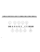
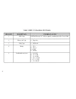
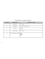
Page 36: ...VEHICLE IDENTIFICATION NUMBER EBR 1190RS MODELS 36 ...
Page 39: ...NOTES 39 ...
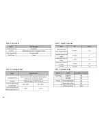
Page 42: ...Table 5 Drivetrain Table 6 Cooling System Table 7 Liquid Capacities Table 8 Sprocket teeth 42 ...
Page 43: ...Table 9 Transmission Gear Ratios Table 11 Tires Table 10 Bulb Chart 43 ...
Page 44: ...Table 12 Dimensions Table 13 Weights 44 ...
Page 64: ...Table 15 64 ...
Page 66: ...Figure 24 Upshift Pattern Figure 25 Downshift Pattern 66 ...
Page 71: ...Maximum Fill Level is at Bottom of Baffle Figure 29 71 ...
Page 84: ...Figure 34 Seat Fasteners Seat removal 4 T 30 screws 84 ...
Page 92: ...92 Notes ...
Page 93: ...93 Notes ...
Page 116: ...Figure 52 Adjustment Measurement 35 mm Adjustment Distance 116 ...
Page 117: ...117 Notes ...
Page 176: ...176 ...
Page 177: ...177 ...
Page 178: ...178 ...


