


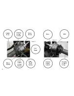


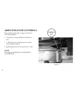

Turn Signal Switch
See Figure 4. The left/right turn signal switch is located
on the left hand controls and activates the front and rear
turn signal flashers.
- Push the turn signal switch to the right to acti-
vate the right front and rear turn signal flashers.
- Push the turn signal switch to the left to activate
the left front and rear turn signal flashers.
- Press the turn signal switch button manually to
cancel the turn signal.
NOTE
If signaling to turn in one direction and the switch is de-
pressed towards the opposite direction, the first signal is
cancelled and the opposite side begins flashing.
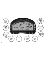
See Figure 6. The green left or right turn signal indicator
will flash when the turn signals are in use.
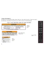
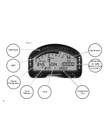
INSTRUMENT CLUSTER
LCD Screen
See Figure 6. The LCD Screen displays a digital speed-
ometer, odometer, clock, and text messages. The LCD
screen is illuminated when the ignition key switch is in
the ON or PARKED position. See CONTROLS AND
INDICATORS, LCD Screen.
Tachometer
See OPERATING RECOMMENDATIONS section.
Do not operate the engine above maximum safe RPM
as shown under OPERATION . Lower the RPM by
up shifting to a higher gear or reducing the amount
of throttle. Failure to lower RPM may cause equip-
ment damage.
The tachometer displays engine speed in revolutions per
minute (RPM x 1000). As the tachometer approaches
the redline, the LEDs at the top of the Instrument Clus-
ter light from green to yellow to red as RPM is in-
creased.
54
Summary of Contents for EBR 1190RS 2013
Page 1: ...2013 EBR OWNERS MANUAL EBR 1190RS MODEL Part Number C1000 2B6 1 ...
Page 3: ...3 ...
Page 23: ...TABLE OF CONTENTS Notes 23 ...
Page 24: ...TABLE OF CONTENTS Notes 24 ...
Page 36: ...VEHICLE IDENTIFICATION NUMBER EBR 1190RS MODELS 36 ...
Page 39: ...NOTES 39 ...
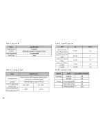
Page 42: ...Table 5 Drivetrain Table 6 Cooling System Table 7 Liquid Capacities Table 8 Sprocket teeth 42 ...
Page 43: ...Table 9 Transmission Gear Ratios Table 11 Tires Table 10 Bulb Chart 43 ...
Page 44: ...Table 12 Dimensions Table 13 Weights 44 ...
Page 64: ...Table 15 64 ...
Page 66: ...Figure 24 Upshift Pattern Figure 25 Downshift Pattern 66 ...
Page 71: ...Maximum Fill Level is at Bottom of Baffle Figure 29 71 ...
Page 84: ...Figure 34 Seat Fasteners Seat removal 4 T 30 screws 84 ...
Page 92: ...92 Notes ...
Page 93: ...93 Notes ...
Page 116: ...Figure 52 Adjustment Measurement 35 mm Adjustment Distance 116 ...
Page 117: ...117 Notes ...
Page 176: ...176 ...
Page 177: ...177 ...
Page 178: ...178 ...