


5
4. Layout and connections
Dual port ethernet option board installation manual
MN032004EN October 2017 www.eaton.com
4. Layout and connections
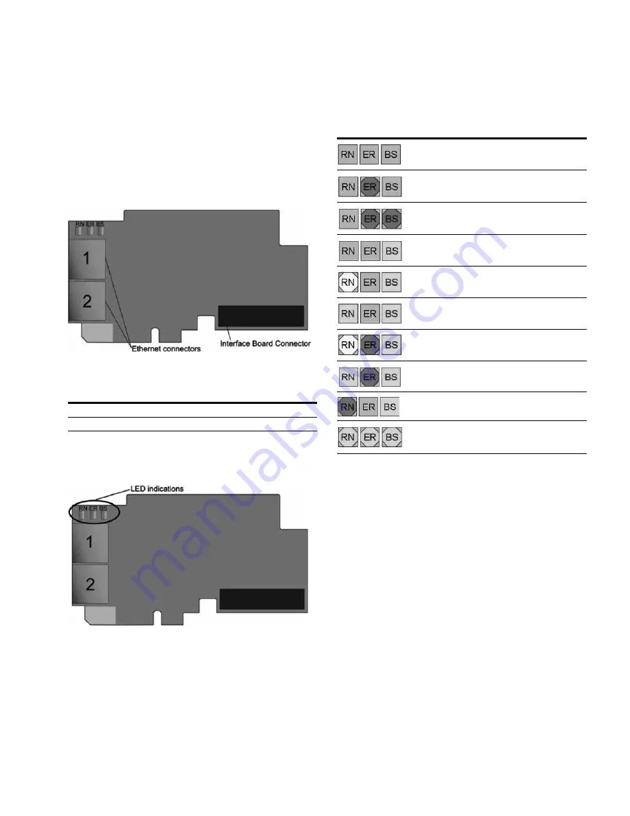
The Eaton OPTE9 Dual Port Ethernet option board is
connected to the Ethernet bus using the standard RJ45
connectors (1 and 2). The communication between the
control board and the AC drive takes place through a
standard Eaton Interface Board Connector.
4.1 Layout and connections
Figure 1. The OPTE9 option board
Table 6. OPTE9 Ethernet ports
Ethernet port
Description
1
Ethernet port 1 (PHY1)
2
Ethernet port 2 (PHY2)
4.2 LED Indications
Figure 2. The OPTE9 option board LED indicators
The table below lists possible LED combinations and their
meanings. When the EtherNet/IP is active, the option board
follows CIP standard for LED indications. Therefore, the
indications described in Table 7 do not apply. See
Chapter 9.1.4 “LED functionality”.
Table 7. List of possible LED combinations
LED combinations
Description
No power. All LEDs are OFF.
Option board firmware is corrupted or its software
is missing. ER is blinking (0.25s ON/0.25s OFF)
Option board failure. Option board is not
operational. BS and possibly ER are blinking
(2.5s ON/2.5s OFF)
Option board is operational.
Protocol is ready for communications. RN is blinking
(2.5s ON/2.5s OFF).
Protocol is communicating.
Protocol communication fault. ER is blinking to
indicate a fault. RN is blinking to indicate that
protocol is again ready for communications.
Protocol is communicating with an active fault. ER
is blinking.
Duplicate IP address detected. RN is blinking.
Profinet IO only!
In node flashing test all three
LEDs are blinking.
4.2.1 Profinet IO
When using the “Node Flashing Test” function, you can
determine to which device you are directly connected. For
example, in Siemens S7, by using the menu command “PLC
> Diagnostics/Setting > Node Flashing Test...” you can
identify the station directly connected to the PG/PC if all
three LEDs are flashing green.
4.3 Ethernet devices
The common-use cases of Ethernet devices are ‘human
to machine’ and ‘machine to machine’. The basic features
of these two cases are presented in the pictures below.
4.3.1 Human to machine
Requirements:
– Graphical User Interface
– Relatively slow communication in use