SD-410-QS (H) (06/15)
Page 47
9.
If there are many bubbles in the INLINE sight glass,
as shown in Figure 33,
additional refrigerant is required. Repeat step 7 until the INLINE sight glass clears or
has a trickle of bubbles as shown in Figure 34 or 35, respectively, but DO NOT ADD
MORE THAN THE FOLLOWING AMOUNTS OF REFRIGERANT TO THE SYSTEM
DURING THIS PROCESS:
Nominal System Tonnage
2.0, 2.5
3.0, 3.5, 4.0, 4.5, 5.0
Maximum Additional Refrigerant
6 lbs
10 lbs
10.
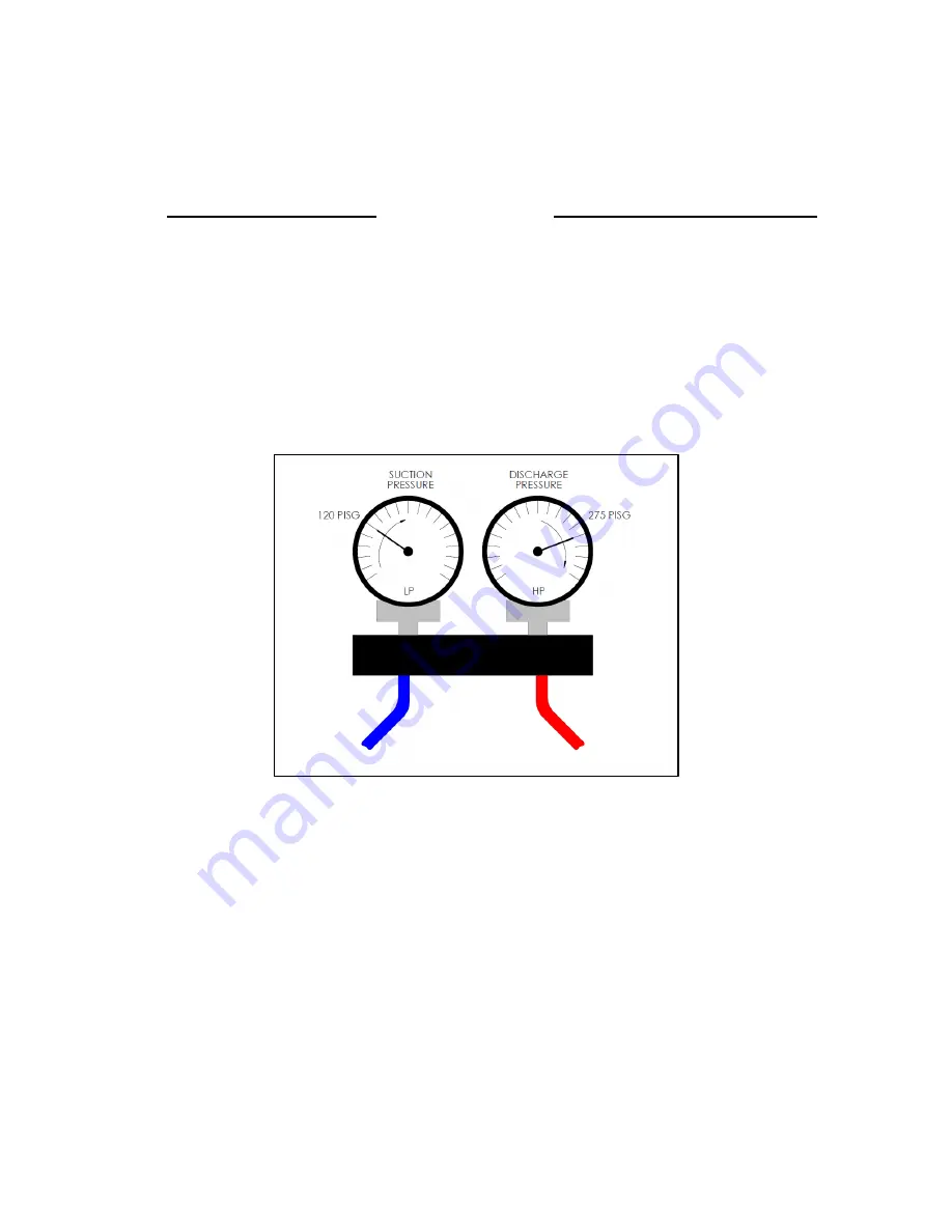
When the suction pressure is at least 120 psig and the INLINE sight glass
shows refrigerant flow as clear or having a trickle of bubbles
, the next step is to
monitor the discharge pressure until it rises to 275 psig or greater
, as shown in
Figure 36. When these conditions are met, proceed to step 11, adjustment of the
TXV superheat.
Figure 36. Minimum Suction and Discharge Pressures
11. The TXV is to be adjusted to provide 10ºF to 15ºF superheat while running in
cooling mode. The first step is to utilize the final charging port and LP gage in
Figure 32 to measure suction pressure. Next, apply a thermocouple at the
compressor suction port as shown in Figure 32 by attaching the thermocouple lead
with electrical tape, and wrapping with ½” thick insulation.
12.
Using an accurate temperature indicator, read the suction temperature at the
compressor suction port.
Read the suction pressure at the final charging port on
the LP gage.
13. Enter the Pressure-Temperature Table in Figure 37 and for the suction pressure
read the LP gage, and determine the saturation temperature (evaporating
temperature) from the chart, interpolating if necessary.
Summary of Contents for AVS-0030-A
Page 15: ...SD 410 QS H 06 15 Page 15 Figure 8a SD H Compressor Unit Electrical Ladder Diagram 230 1 60...
Page 16: ...SD 410 QS H 06 15 Page 16 Figure 8b SD H Compressor Unit Electrical Schematic Diagram 230 1 60...
Page 17: ...SD 410 QS H 06 15 Page 17 Figure 9a SD H Compressor Unit Electrical Ladder Diagram 230 3 60...
Page 18: ...SD 410 QS H 06 15 Page 18 Figure 9b SD H Compressor Unit Electrical Schematic Diagram 230 3 60...
Page 29: ...SD 410 QS H 06 15 Page 29 Figure 15 Disassembled Plug Connector...
Page 49: ...SD 410 QS H 06 15 Page 49 Figure 38 Cooling Mode Start Up...
Page 58: ...SD 410 QS H 06 15 Page 58...
Page 59: ...SD 410 QS H 06 15 Page 59...
Page 60: ...SD 410 QS H 06 15 Page 60...
Page 61: ...SD 410 QS H 06 15 Page 61...
Page 62: ...SD 410 QS H 06 15 Page 62...
Page 63: ...SD 410 QS H 06 15 Page 63...


