SD-410-QS (H) (06/15)
Page 14
Compressor
Unit Model
Compressor
Model
Voltage/Phase/
Hz
Voltage
LRA
RLA
MCA
MFS
Min.
Max.
-024-1C
ZP25K6E-PFV
230-1-60
207
253
72.5
15.0
18.0
30
-024-2C
ZP25K63-TF5
230-3-60
207
253
61.4
9.8
12.0
20
-030-1C
ZP31K5E-PFV
230-1-60
207
253
78.0
18.6
23.0
35
-030-2C
ZP31K5E-TF5
230-3-60
207
253
73.0
11.6
14.0
20
-036-1C
ZP38K5E-PFV
230-1-60
207
253
109.0
22.1
27.0
40
-036-2C
ZP38K5E-TP5
230-3-60
207
253
83.1
15.1
19.0
30
-042-1C
ZP44K5E-PFV
230-1-60
207
253
135.0
23.9
29.0
50
-042-2C
ZP44K5E-TF5
230-3-60
207
253
98.0
16.1
20.0
30
-048-1C
ZP51K5E-PFV
230-1-60
207
253
134.0
29.4
36.0
60
-048-2C
ZP51K5E-TF5
230-3-60
207
253
110.0
17.8
22.0
35
-054-1C
ZP57K5E-PFV
230-1-60
207
253
178.0
31.6
39.0
60
-054-2C
ZP57K5E-TF5
230-3-60
207
253
136.0
21.4
26.0
40
-060-1C
ZP61K5E-PFV
230-1-60
207
253
178.0
34.3
42.0
60
-060-2C
ZP61K5E-TF5
230-3-60
207
253
136.0
21.9
27.0
40
LRA = Locked Rotor Amps
RLA = Rated Load Amps
MCA = Minimum Circuit Ampacity
MFS = Maximum Fuse or HACR Circuit Breaker Size
(External)
AWS = Consult NEC and Local Codes
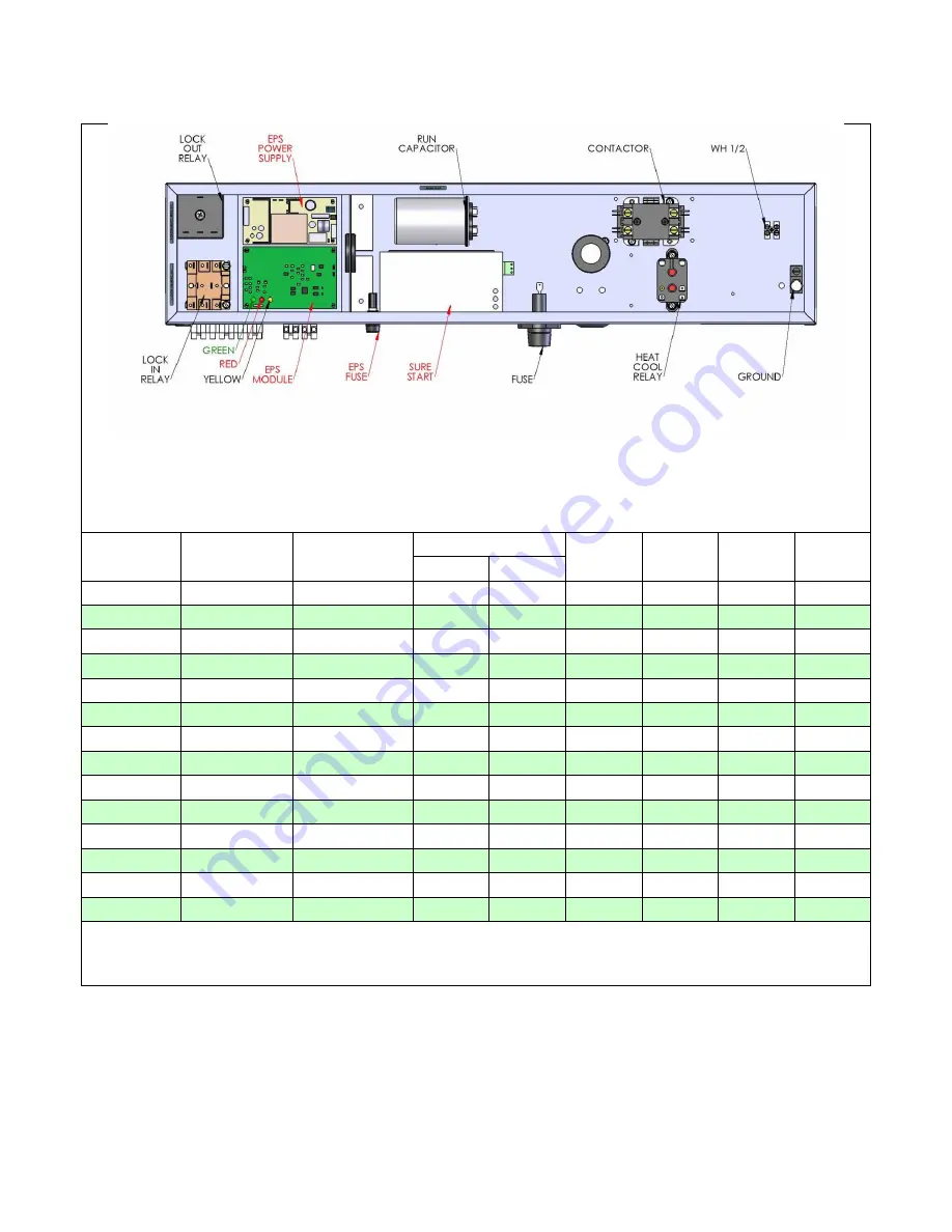
Figure 7. SD(H) Electric Box Components & Electrical Data
Summary of Contents for AVS-0030-A
Page 15: ...SD 410 QS H 06 15 Page 15 Figure 8a SD H Compressor Unit Electrical Ladder Diagram 230 1 60...
Page 16: ...SD 410 QS H 06 15 Page 16 Figure 8b SD H Compressor Unit Electrical Schematic Diagram 230 1 60...
Page 17: ...SD 410 QS H 06 15 Page 17 Figure 9a SD H Compressor Unit Electrical Ladder Diagram 230 3 60...
Page 18: ...SD 410 QS H 06 15 Page 18 Figure 9b SD H Compressor Unit Electrical Schematic Diagram 230 3 60...
Page 29: ...SD 410 QS H 06 15 Page 29 Figure 15 Disassembled Plug Connector...
Page 49: ...SD 410 QS H 06 15 Page 49 Figure 38 Cooling Mode Start Up...
Page 58: ...SD 410 QS H 06 15 Page 58...
Page 59: ...SD 410 QS H 06 15 Page 59...
Page 60: ...SD 410 QS H 06 15 Page 60...
Page 61: ...SD 410 QS H 06 15 Page 61...
Page 62: ...SD 410 QS H 06 15 Page 62...
Page 63: ...SD 410 QS H 06 15 Page 63...


