SD-410-QS (H) (06/15)
Page 39
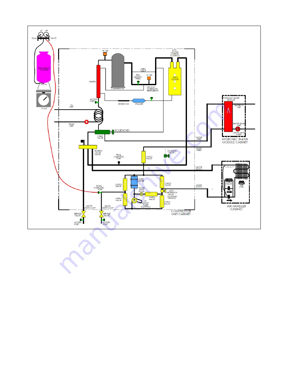
Figure 27. Initial Charge of SD(H) System
2. Open the refrigerant container valve and inject liquid refrigerant into the initial charging
port as shown in Figure 27.
3. Charge with liquid refrigerant until 3 pounds of refrigerant per ton of system capacity, has
entered the system.
Liquid entering the system at the initial charging port goes directly to the system earth
loops, it does not go to the compressor. Should the pressures equalize and prevent the
intended charge from entering completely, terminate the process of initial charging. Note
and document the amount of refrigerant.
4. When the initial refrigerant charge (see step 3 above) has entered the system, close the
refrigerant container valve and disconnect the refrigerant hose from the initial charging
port. Note and document the amount of refrigerant.
5. The system has now been initially charged.
Summary of Contents for AVS-0030-A
Page 15: ...SD 410 QS H 06 15 Page 15 Figure 8a SD H Compressor Unit Electrical Ladder Diagram 230 1 60...
Page 16: ...SD 410 QS H 06 15 Page 16 Figure 8b SD H Compressor Unit Electrical Schematic Diagram 230 1 60...
Page 17: ...SD 410 QS H 06 15 Page 17 Figure 9a SD H Compressor Unit Electrical Ladder Diagram 230 3 60...
Page 18: ...SD 410 QS H 06 15 Page 18 Figure 9b SD H Compressor Unit Electrical Schematic Diagram 230 3 60...
Page 29: ...SD 410 QS H 06 15 Page 29 Figure 15 Disassembled Plug Connector...
Page 49: ...SD 410 QS H 06 15 Page 49 Figure 38 Cooling Mode Start Up...
Page 58: ...SD 410 QS H 06 15 Page 58...
Page 59: ...SD 410 QS H 06 15 Page 59...
Page 60: ...SD 410 QS H 06 15 Page 60...
Page 61: ...SD 410 QS H 06 15 Page 61...
Page 62: ...SD 410 QS H 06 15 Page 62...
Page 63: ...SD 410 QS H 06 15 Page 63...


