SD-410-QS (H) (06/15)
Page 43
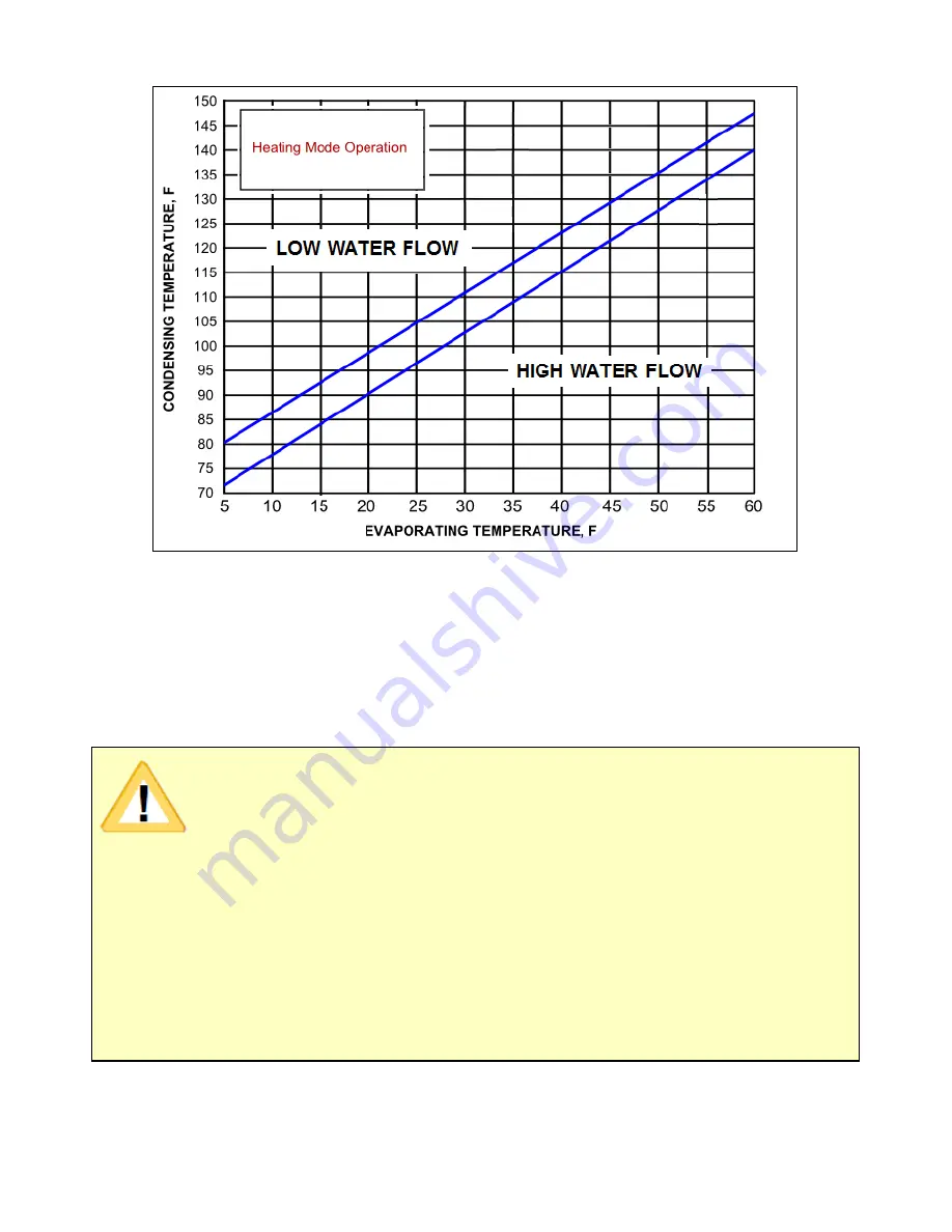
Figure 31. Hydronic System Performance Parameters
8. Check the suction saturation temperature to verify that it is within ±3°F for the measured
suction pressure. The suction temperature should be approximately 15 to 20°F lower
than the local earth temperature.
Cool Mode Start-Up
IMPORTANT!
Be sure the return air to the air handler is maintained in the range of
70ºF to 80ºF.
If site conditions prevent maintaining an air handler return air
temperature between 70ºF and 80ºF, the cooling system start-up steps
can be completed at a later time. If the cooling mode start-up process is
delayed, the system can run in heat mode only and the cooling mode
must be disabled until the cooling mode start-up process is initiated. If
the cooling mode start-up process is initiated after running the system
in heat only mode, the system should remain OFF for 48 hours after
running in the heat mode to allow the earth temperature surrounding the
earth loops to stabilize.
Summary of Contents for AVS-0030-A
Page 15: ...SD 410 QS H 06 15 Page 15 Figure 8a SD H Compressor Unit Electrical Ladder Diagram 230 1 60...
Page 16: ...SD 410 QS H 06 15 Page 16 Figure 8b SD H Compressor Unit Electrical Schematic Diagram 230 1 60...
Page 17: ...SD 410 QS H 06 15 Page 17 Figure 9a SD H Compressor Unit Electrical Ladder Diagram 230 3 60...
Page 18: ...SD 410 QS H 06 15 Page 18 Figure 9b SD H Compressor Unit Electrical Schematic Diagram 230 3 60...
Page 29: ...SD 410 QS H 06 15 Page 29 Figure 15 Disassembled Plug Connector...
Page 49: ...SD 410 QS H 06 15 Page 49 Figure 38 Cooling Mode Start Up...
Page 58: ...SD 410 QS H 06 15 Page 58...
Page 59: ...SD 410 QS H 06 15 Page 59...
Page 60: ...SD 410 QS H 06 15 Page 60...
Page 61: ...SD 410 QS H 06 15 Page 61...
Page 62: ...SD 410 QS H 06 15 Page 62...
Page 63: ...SD 410 QS H 06 15 Page 63...


