SD-410-QS (H) (06/15)
Page 40
Final Charge
It is critical to control the conditions under which the compressor unit operates while final charging the
system.
Final charging must be done in HEAT mode.
Air Handler Systems
The return air to the air handler during final charging is to be maintained in the range of 70°F
to 80°F. If necessary, the air can be warmed with electric supplemental heat in the air handler.
(Shunt “R” to “W2” at the terminal block.)
Hydronic Systems
If heating is provided through a hydronic water module, HWM, the circulating water is to be
maintained in the 95°F to 105°F range.
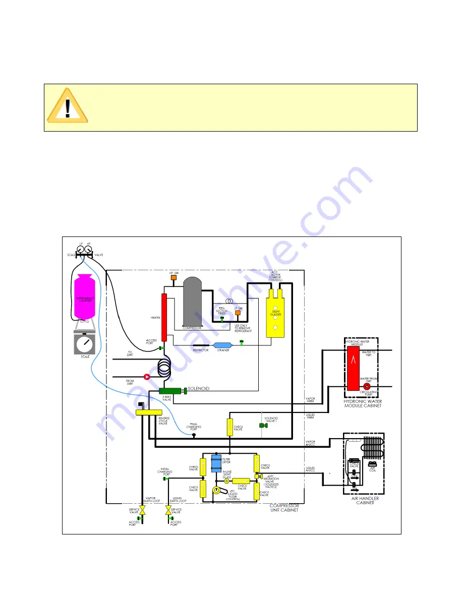
The final charging procedure is as follows, with the final charging set up described in Figure 28.
Figure 28. Final Charge of SD(H) System
IMPORTANT!
For this SD(H) Model, final charging should be done using the AIR
HANDLER in HEAT MODE.
Summary of Contents for AVS-0030-A
Page 15: ...SD 410 QS H 06 15 Page 15 Figure 8a SD H Compressor Unit Electrical Ladder Diagram 230 1 60...
Page 16: ...SD 410 QS H 06 15 Page 16 Figure 8b SD H Compressor Unit Electrical Schematic Diagram 230 1 60...
Page 17: ...SD 410 QS H 06 15 Page 17 Figure 9a SD H Compressor Unit Electrical Ladder Diagram 230 3 60...
Page 18: ...SD 410 QS H 06 15 Page 18 Figure 9b SD H Compressor Unit Electrical Schematic Diagram 230 3 60...
Page 29: ...SD 410 QS H 06 15 Page 29 Figure 15 Disassembled Plug Connector...
Page 49: ...SD 410 QS H 06 15 Page 49 Figure 38 Cooling Mode Start Up...
Page 58: ...SD 410 QS H 06 15 Page 58...
Page 59: ...SD 410 QS H 06 15 Page 59...
Page 60: ...SD 410 QS H 06 15 Page 60...
Page 61: ...SD 410 QS H 06 15 Page 61...
Page 62: ...SD 410 QS H 06 15 Page 62...
Page 63: ...SD 410 QS H 06 15 Page 63...


