SD-410-QS (H) (06/15)
Page 30
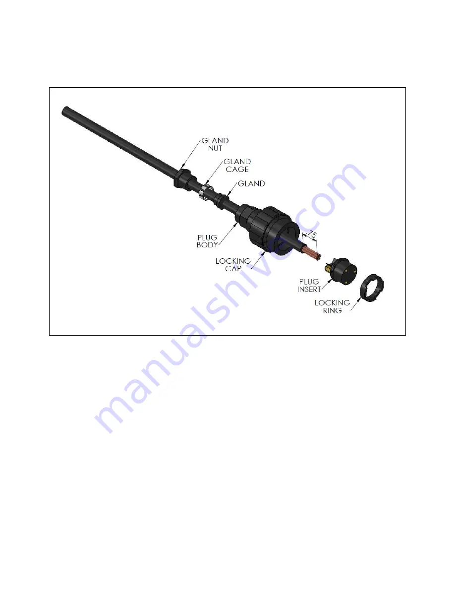
Strip the insulation from the multi-strand anode wire back approximately ¾ inch from the end and,
while keeping the strands together, push the anode wire through the
gland nut, gland cage, gland
and
plug body
as shown in Figure 16. Loosen one of the two screw terminals on the
plug insert
to
receive all of the strands of anode wire on one terminal.
Figure 16. Anode Wire Insertion
After inserting all strands of the anode wire into one of the terminals on the
plug insert
, tighten the
wire in place by tightening the screw on that terminal. Once tightened, push the
plug insert
back into
the
plug body
as shown in Figure 17 until it is firmly seated. Engage the
locking ring
with threads in
the
plug body
and turn clockwise with the
sealing cap assembly tool
until the
lock ring
is firmly
seated and tight against the
plug insert.
Summary of Contents for AVS-0030-A
Page 15: ...SD 410 QS H 06 15 Page 15 Figure 8a SD H Compressor Unit Electrical Ladder Diagram 230 1 60...
Page 16: ...SD 410 QS H 06 15 Page 16 Figure 8b SD H Compressor Unit Electrical Schematic Diagram 230 1 60...
Page 17: ...SD 410 QS H 06 15 Page 17 Figure 9a SD H Compressor Unit Electrical Ladder Diagram 230 3 60...
Page 18: ...SD 410 QS H 06 15 Page 18 Figure 9b SD H Compressor Unit Electrical Schematic Diagram 230 3 60...
Page 29: ...SD 410 QS H 06 15 Page 29 Figure 15 Disassembled Plug Connector...
Page 49: ...SD 410 QS H 06 15 Page 49 Figure 38 Cooling Mode Start Up...
Page 58: ...SD 410 QS H 06 15 Page 58...
Page 59: ...SD 410 QS H 06 15 Page 59...
Page 60: ...SD 410 QS H 06 15 Page 60...
Page 61: ...SD 410 QS H 06 15 Page 61...
Page 62: ...SD 410 QS H 06 15 Page 62...
Page 63: ...SD 410 QS H 06 15 Page 63...


