SD-410-QS (H) (06/15)
Page 42
For Air Systems:
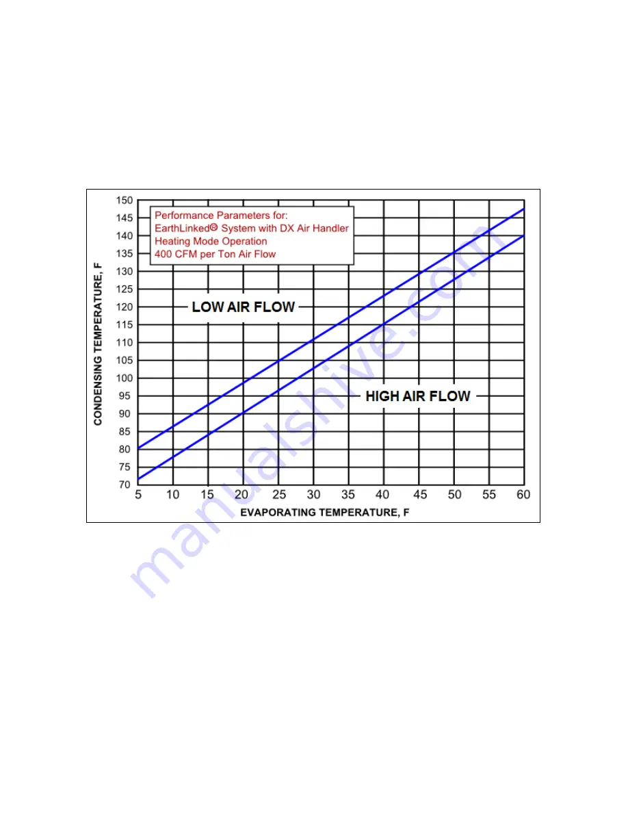
In Figure 30, locate the evaporating temperature on the horizontal axis. The
corresponding condensing temperature reading should fall between the upper and lower
parallel lines in Figure 30.
The temperature profile in Figure 30 is valid for the air handler systems with an air
flow of 400CFM per Ton
. If condensing temperature is above acceptable range, the air
flow is low. If condensing temperature is below the acceptable range, air flow is too high.
Adjust air flow as appropriate.
Figure 30. Air System Performance Parameters
For Hydronic Systems:
In Figure 31, locate the evaporating temperature on the horizontal axis. The
corresponding condensing temperature reading should fall between the upper and lower
parallel lines in Figure 31.
The temperature profile in Figure 31 is valid for hydronic systems with the correct
heat exchanger water flow
. If condensing temperature is above acceptable range, the
water flow is low. If condensing temperature is below the acceptable range, water flow is
too high.
Adjust water flow as appropriate.
Summary of Contents for AVS-0030-A
Page 15: ...SD 410 QS H 06 15 Page 15 Figure 8a SD H Compressor Unit Electrical Ladder Diagram 230 1 60...
Page 16: ...SD 410 QS H 06 15 Page 16 Figure 8b SD H Compressor Unit Electrical Schematic Diagram 230 1 60...
Page 17: ...SD 410 QS H 06 15 Page 17 Figure 9a SD H Compressor Unit Electrical Ladder Diagram 230 3 60...
Page 18: ...SD 410 QS H 06 15 Page 18 Figure 9b SD H Compressor Unit Electrical Schematic Diagram 230 3 60...
Page 29: ...SD 410 QS H 06 15 Page 29 Figure 15 Disassembled Plug Connector...
Page 49: ...SD 410 QS H 06 15 Page 49 Figure 38 Cooling Mode Start Up...
Page 58: ...SD 410 QS H 06 15 Page 58...
Page 59: ...SD 410 QS H 06 15 Page 59...
Page 60: ...SD 410 QS H 06 15 Page 60...
Page 61: ...SD 410 QS H 06 15 Page 61...
Page 62: ...SD 410 QS H 06 15 Page 62...
Page 63: ...SD 410 QS H 06 15 Page 63...


