SD-410-QS (H) (06/15)
Page 35
System Start-Up
Evacuation
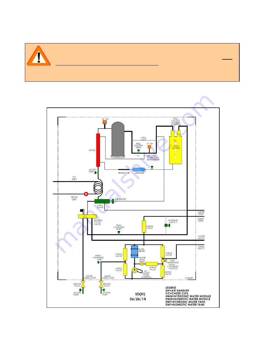
Prior to system start-up, evacuation of the system is accomplished through the compressor unit. All
of the refrigerant containing components in the compressor unit are illustrated in Figures 24 and 25.
The evacuation and charging process will utilize an access port, initial charging port and final charging
port.
Figure 24. SD(H) Internal Flow Schematic
CAUTION!
During the Evacuation and Initial Charging processes, be sure that ALL
power to the EarthLinked
®
System is OFF. This includes the
compressor unit, air handler and all other electrically powered system
components.
Summary of Contents for AVS-0030-A
Page 15: ...SD 410 QS H 06 15 Page 15 Figure 8a SD H Compressor Unit Electrical Ladder Diagram 230 1 60...
Page 16: ...SD 410 QS H 06 15 Page 16 Figure 8b SD H Compressor Unit Electrical Schematic Diagram 230 1 60...
Page 17: ...SD 410 QS H 06 15 Page 17 Figure 9a SD H Compressor Unit Electrical Ladder Diagram 230 3 60...
Page 18: ...SD 410 QS H 06 15 Page 18 Figure 9b SD H Compressor Unit Electrical Schematic Diagram 230 3 60...
Page 29: ...SD 410 QS H 06 15 Page 29 Figure 15 Disassembled Plug Connector...
Page 49: ...SD 410 QS H 06 15 Page 49 Figure 38 Cooling Mode Start Up...
Page 58: ...SD 410 QS H 06 15 Page 58...
Page 59: ...SD 410 QS H 06 15 Page 59...
Page 60: ...SD 410 QS H 06 15 Page 60...
Page 61: ...SD 410 QS H 06 15 Page 61...
Page 62: ...SD 410 QS H 06 15 Page 62...
Page 63: ...SD 410 QS H 06 15 Page 63...


