


SD-410-QS (H) (06/15)
Page 41
1. Re-connect the red HP hose, after purging with a trickle of refrigerant, (from the initial
charging port in Figure 27) to the access port as shown in Figure 28. Continue
measuring the refrigerant charge weight as shown in Figure 28.
2.
Be sure that air entering the air handler is between 70°F and 80°F. If the system is
a hydronic primary circuit, circulating water is to be held between 95°F and 105°F.
3. Close the HP valve.
Then turn the system on in the HEAT mode
.
4. Initiate final charging by
SLOWLY
opening the refrigerant container valve and the gage
manifold LP valve to allow liquid refrigerant to enter the final charging port
SLOWLY
.
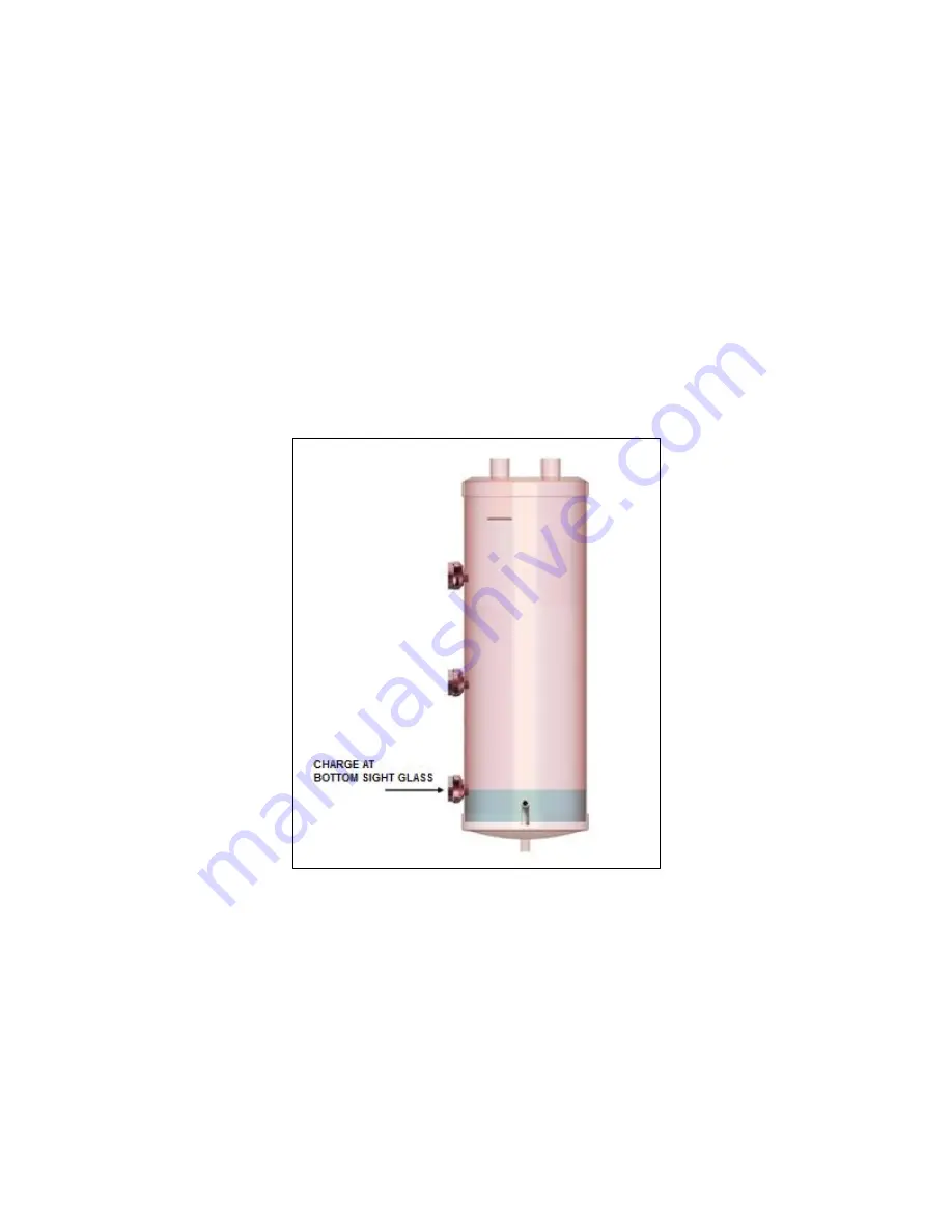
5. Adding liquid refrigerant will raise the liquid level in the ACC. Continue to add liquid
refrigerant to the system until the liquid level has reached the bottom sight glass, as
shown in Figure 29.
6.
When the liquid level is at the bottom sight glass, as shown in Figure 29, turn the
refrigerant container valve OFF.
Figure 29. Charge at Bottom Sight Glass
7. When the system has run for 20 minutes (in HEAT mode), read the evaporating
temperature and condensing temperature.
The evaporating temperature can be read by attaching a thermocouple lead to the Earth
Loop Vapor Line with electrical tape, then wrapped with ½” thick insulation. The
condensing temperature can be read by attaching a thermocouple lead to the Air
Handler/CC/HWM liquid line coming into the compressor unit with electrical tape, then
wrapped with ½” thick insulation. Use an accurate temperature indicator.
Summary of Contents for AVS-0030-A
Page 15: ...SD 410 QS H 06 15 Page 15 Figure 8a SD H Compressor Unit Electrical Ladder Diagram 230 1 60...
Page 16: ...SD 410 QS H 06 15 Page 16 Figure 8b SD H Compressor Unit Electrical Schematic Diagram 230 1 60...
Page 17: ...SD 410 QS H 06 15 Page 17 Figure 9a SD H Compressor Unit Electrical Ladder Diagram 230 3 60...
Page 18: ...SD 410 QS H 06 15 Page 18 Figure 9b SD H Compressor Unit Electrical Schematic Diagram 230 3 60...
Page 29: ...SD 410 QS H 06 15 Page 29 Figure 15 Disassembled Plug Connector...
Page 49: ...SD 410 QS H 06 15 Page 49 Figure 38 Cooling Mode Start Up...
Page 58: ...SD 410 QS H 06 15 Page 58...
Page 59: ...SD 410 QS H 06 15 Page 59...
Page 60: ...SD 410 QS H 06 15 Page 60...
Page 61: ...SD 410 QS H 06 15 Page 61...
Page 62: ...SD 410 QS H 06 15 Page 62...
Page 63: ...SD 410 QS H 06 15 Page 63...