SD-410-QS (H) (06/15)
Page 36
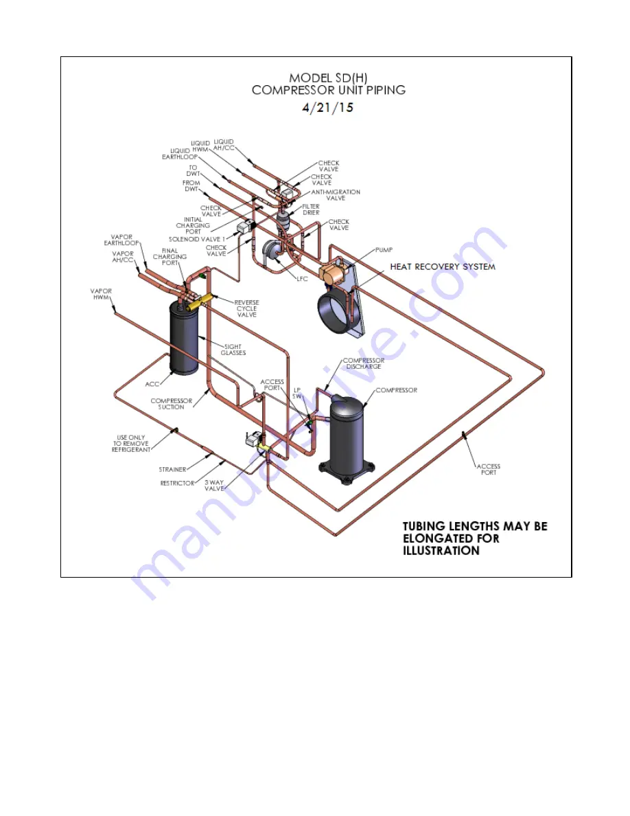
Figure 25. SD(H) Piping
Refer to Figure 26 and the following procedure:
1. Carefully vent any pressurized charge from the compressor and system..
2. After venting the pressurized system, connect the Gage Block and Hoses as shown in
Figure 26. LP and HP valves are fully open. Both Service Valves are fully opened.
3. As illustrated in Figure 26, connect a good quality Digital Micron Gage to the Liquid
Service Valve Access Port with an Isolation Hose/Valve. Connect a quality Vacuum Pump
(at least 6 CFM capacity) to the Gage Block.
Summary of Contents for AVS-0030-A
Page 15: ...SD 410 QS H 06 15 Page 15 Figure 8a SD H Compressor Unit Electrical Ladder Diagram 230 1 60...
Page 16: ...SD 410 QS H 06 15 Page 16 Figure 8b SD H Compressor Unit Electrical Schematic Diagram 230 1 60...
Page 17: ...SD 410 QS H 06 15 Page 17 Figure 9a SD H Compressor Unit Electrical Ladder Diagram 230 3 60...
Page 18: ...SD 410 QS H 06 15 Page 18 Figure 9b SD H Compressor Unit Electrical Schematic Diagram 230 3 60...
Page 29: ...SD 410 QS H 06 15 Page 29 Figure 15 Disassembled Plug Connector...
Page 49: ...SD 410 QS H 06 15 Page 49 Figure 38 Cooling Mode Start Up...
Page 58: ...SD 410 QS H 06 15 Page 58...
Page 59: ...SD 410 QS H 06 15 Page 59...
Page 60: ...SD 410 QS H 06 15 Page 60...
Page 61: ...SD 410 QS H 06 15 Page 61...
Page 62: ...SD 410 QS H 06 15 Page 62...
Page 63: ...SD 410 QS H 06 15 Page 63...


