SD-410-QS (H) (06/15)
Page 25
Internal Heat Recovery System
The SD(H) Compressor Unit has a built-in Heat Recovery System for the purpose of providing
supplemental water heating during heating and/or cooling operation.
The Heat Recovery System
does not replace the standard storage water heater
sized for the application.
Use of the Heat Recovery System to heat water in the heating season will increase the heating
load on the space heating equipment by 2,000 BTUH for each adult and teenager occupant.
This must be factored into the sizing of the space heating equipment to maintain comfort
during the heating season.
Operating the Heat Recovery System during the heating season will
reduce the cost of heating water, compared to heating water with a standard electric water heater.
Operation of the Heat Recovery System during the cooling season utilizes waste heat from the
cooling system and does not impose an additional load on the cooling operation.
The built-in Heat Recovery System comes factory wired to heat water during heating and
cooling seasons.
To have the Heat Recovery System
operate during cooling season only
, the
SD Series Heating Option Kit, Model SDHO-1872
is available for field installation.
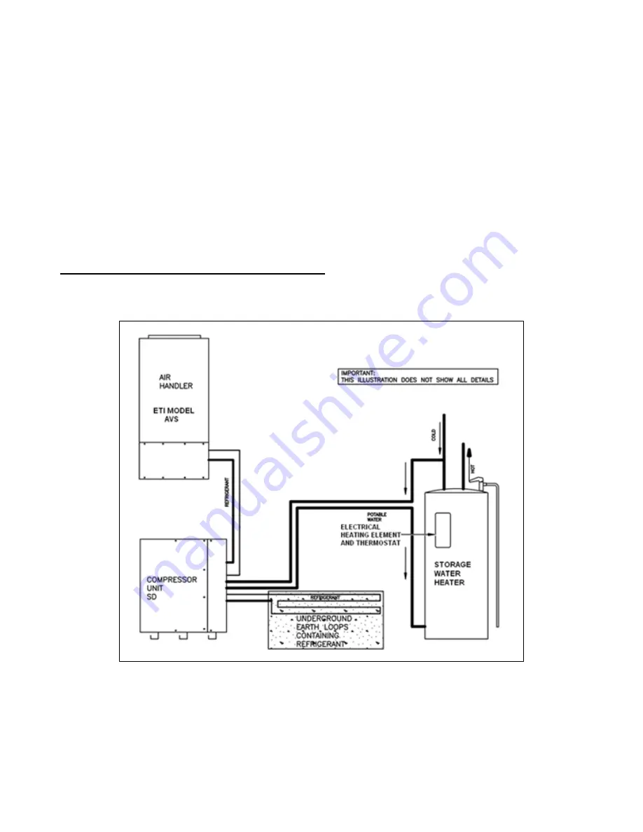
The Heat Recovery System may be plumbed into an existing standard water heater as illustrated in
Figure 12.
Figure 12. Standard Storage Water Heater
– Service Connections
Alternatively, the Heat Recovery System may be plumbed to the
ETI Series GSTE storage water
heater as shown in Figures 13a and 13b
. The Series GSTE storage water heaters are preferred
because the heat recovery system ports are designed to provide more efficient heat exchange within
the storage water heater.
Summary of Contents for AVS-0030-A
Page 15: ...SD 410 QS H 06 15 Page 15 Figure 8a SD H Compressor Unit Electrical Ladder Diagram 230 1 60...
Page 16: ...SD 410 QS H 06 15 Page 16 Figure 8b SD H Compressor Unit Electrical Schematic Diagram 230 1 60...
Page 17: ...SD 410 QS H 06 15 Page 17 Figure 9a SD H Compressor Unit Electrical Ladder Diagram 230 3 60...
Page 18: ...SD 410 QS H 06 15 Page 18 Figure 9b SD H Compressor Unit Electrical Schematic Diagram 230 3 60...
Page 29: ...SD 410 QS H 06 15 Page 29 Figure 15 Disassembled Plug Connector...
Page 49: ...SD 410 QS H 06 15 Page 49 Figure 38 Cooling Mode Start Up...
Page 58: ...SD 410 QS H 06 15 Page 58...
Page 59: ...SD 410 QS H 06 15 Page 59...
Page 60: ...SD 410 QS H 06 15 Page 60...
Page 61: ...SD 410 QS H 06 15 Page 61...
Page 62: ...SD 410 QS H 06 15 Page 62...
Page 63: ...SD 410 QS H 06 15 Page 63...


