2-31
D Y N O I N S T A L L A T I O N
Cable Routing
Version 4
Above Ground Model 250i Motorcycle Dynamometer Installation Guide
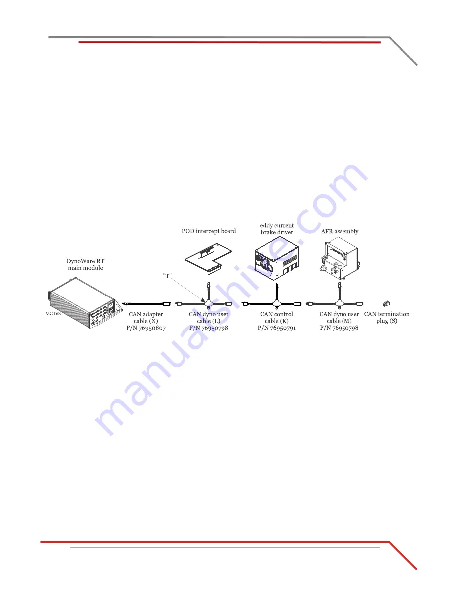
11 Attach the CAN adapter cable (N) to the back of the DynoWare RT main module.
12 Attach the CAN dyno user cable (L) to the CAN adapter cable (N) and route to the
POD intercept board. Attach the CAN dyno user cable (L) to the POD intercept
board.
13 Attach the CAN control cable (K) to the “T” on the CAN dyno user cable (L) and
route to the eddy current brake driver. Attach the CAN control cable (K) to the
eddy current brake driver.
14 Attach the CAN dyno user cable (M) to the “T” on the CAN control cable (K) and
route to the AFR assembly. Attach the CAN dyno user cable (M) to the AFR
assembly.
Note:
The AFR assembly is an optional accessory.
15 Insert the CAN termination plug (S) in the CAN dyno user cable (M).
Note:
If you do not have an eddy current brake and/or AFR assembly, insert the
CAN termination plug (S) at the end of your CAN network cable chain.
Figure 2-26: CAN Network Cable Configuration
16 Route the e-stop cable (G) from P7 on the front panel of the CPI to the back of the
DynoWare RT main module.
17 Route the AFR power cable to the AFR assembly.
18 Insert the O2 sensor(s) into the sensor block on the AFR assembly, plug sensor
connectors into AFR, and tie the sensor cables.
19 Attach the network cable (P) to your network. Refer to “Network Connections” on
20 Route the power cable (Q) from the DIN rail to the back of the DynoWare RT
module.
21 Attach remote atmos cable (A) to the DynoWare RT module and stick the atmos
module to the side of the dyno.
22 Remove the PCV CAN termination plug (R) from the front of the DynoWare RT
module and save for use with the PCV module.
22a Attach the PCV or OBD2 module using the CAN powersports cable (J).
22b Insert the PCV CAN termination plug (R) in the PCV module.
Note:
If you are not using a PCV, be sure to save the PCV CAN termination
plug (R) for future use.


